00193356-02.pdf - 第33页
SIPLACE S-25 HM 2 Assembly Instructions: Component Sensor (Option) for RV12-DLM1 Placement Head 04/2007 Edition 2.5 Assembly Kit, Documentation, Tools, etc. 33 2.5.5 T ools, Expendable Materials – Allen wrench , size 2.5…

2 Assembly Instructions: Component Sensor (Option) for RV12-DLM1 Placement Head SIPLACE S-25 HM
2.5 Assembly Kit, Documentation, Tools, etc. 04/2007 Edition
32
2.5 Assembly Kit, Documentation, Tools, etc.
2.5.1 Assembly Kit for Component Sensor for 12-Segment C+P
(RV12-DLM1), Item no.: 00118021-01
2.5.2 Assembly Kits for SW 503.xx
2.5.3 Assembly Kits for "Modular Head PCB" on HS-50 and S-25 HM
If there is not as yet a modular head PCB on the machine to be assemblied, you need one of the
following assembly kits, each of which contains the pertinent parts for all of the machine’s: 2
2.5.4 Additional Documents Required
-
If applicable, SITEST Software Instructions, V 5.03.xx, Item no.:00193330-01 (G + E)
Qnty.
Designation Item no.:
1
Component sensor assembly SP-12 (incl. cable with connector*) 00367142-01
1
2 socket hex head cap screws M 3 x 12 *)
1
1 socket hex head cap screws M 3 x 14 *)
1
Assembling gauge for component sensor *) 03003110-01
1
Assembly Instructions for Component Sensor
S-25 HM and HS-50
00193356-01
1
Manual for the Placement of 0201 Components, G + E 00191667-04
*) see Fig. 1.5.1
Qnty.
Designation Item no.:
1
Line computer SW 503/1
(Documentation and CD, German and English)
or
00368385-01
1
Line computer SW SIPLACE PRO 1.3 on request
1
SW SIPLACE station 503/1
(Documentation and CD, German and English)
00368293-01
1
Language pack:
CD with GUI and documentation
00368802-01
Qnty.
Designation Item no.:
1
Assembly kit "PCB HS-50" head (modular) 00359489-01 *)
1
Assembly kit "PCB S-23 head (S-25 HM)", modular 00359488-01 *)
*) The assembly instructions "Modular Head PCBs on S-23, S-25 HM, F5 HM,
HS-50" (item no.: 00192393-01, G + E) is included in the assembly kit.
SIPLACE S-25 HM 2 Assembly Instructions: Component Sensor (Option) for RV12-DLM1 Placement Head
04/2007 Edition 2.5 Assembly Kit, Documentation, Tools, etc.
33
2.5.5 Tools, Expendable Materials
– Allen wrench, size 2.5 and oblique-nosed cutting pliers
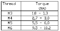
– Torque wrench (see table below)
– Per placement head: 2 cable ties LxW = 140 x 3.6 mm Item no.: 00805141-01
2.5.6 Torques for Screws
Setting the correct torque prevents parts (component sensor, blast air unit) from being loosened
by the travel movement of the gantry.

2 Assembly Instructions: Component Sensor (Option) for RV12-DLM1 Placement Head SIPLACE S-25 HM
2.6 Work Sequence 04/2007 Edition
34
2.6 Work Sequence
2.6.1 Preparatory Steps
: Undock the component trolley from the placement system.
2
: Use the function "gantry in setup position" to move the placement head(s) into the area over
the PCB conveyor.
: If the machine is fitted with a head crash protection unit, fold it up.
: If you assembly the option on a number of placement heads, keep in mind:
You must maintain the existing allocation of the mobile changeover table to the locations 1-4.
: Undock the mobile changeover table(s) from the machine and move it out of the machine.
: Turn the machine OFF and disconnect the machine from the mains.
: If you haven’t already done so, assembly the modular head PCB on each gantry of the PCB
as described in the assembly instructions for modular head PCB on S-23, S-25 HM, F5 HM,
HS-50", item no.: 00192393-01, G + E.
2.6.2 Installing the Assembly Kit
CAUTION
Comply with the ESD regulations while handling the PCBs.
Use the ESD bracelet and connect it to the grounding button on the machine that is provided for
this purpose.
Make certain that NO screws or other parts drop into the machine or the placement head. 2