00193356-02.pdf - 第41页
SIPLACE S-25 HM 2 Assembly Instructions: Component Sensor (Option) for RV12-DLM1 Placement Head 04/2007 Edition 2.6 Work Sequence 41 : Unplug the connector of the round cable (mot or/tachometer) on the modular head PCB (…
2 Assembly Instructions: Component Sensor (Option) for RV12-DLM1 Placement Head SIPLACE S-25 HM
2.6 Work Sequence 04/2007 Edition
40
2.6.3 HS-50: Laying Cable and Making Connections
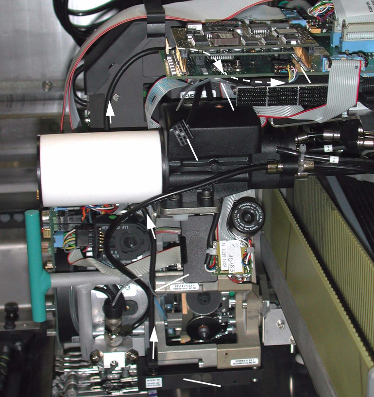
Abb. 2.6.5 HS-50: Laying and Connecting the Component Sensor Cable
Key
1. Component sensor (assembly complete)
2. Route of component sensor cable to the gantry head distributor (on HS-50 and S-25 HM)
3. 1 cable tie (position on HS-50 and S-25 HM)
4. Route of cable under the gantry head distributor -> Detail: see Abb. 2.6.6)
5. Plug-in connector for round cable (motor/tachometer), drawn
6. 1 cable tie on the spacer bolt -> Detail: see Abb. 2.6.6)
7. Plug-in connector of the component sensor cable -> Detail: see Abb. 2.6.6)
2
1
2
1
2
2
2
6
5
7
3
4
SIPLACE S-25 HM 2 Assembly Instructions: Component Sensor (Option) for RV12-DLM1 Placement Head
04/2007 Edition 2.6 Work Sequence
41
: Unplug the connector of the round cable (motor/tachometer) on the modular head PCB (see
Abb. 2.6.5 -> 5).
: Lay the component sensor cable upward toward the modular head PCB and fasten the cable
in the BOTTOM cable run on the placement head, as shown in Abb. 2.6.5 -> 2 and 3.
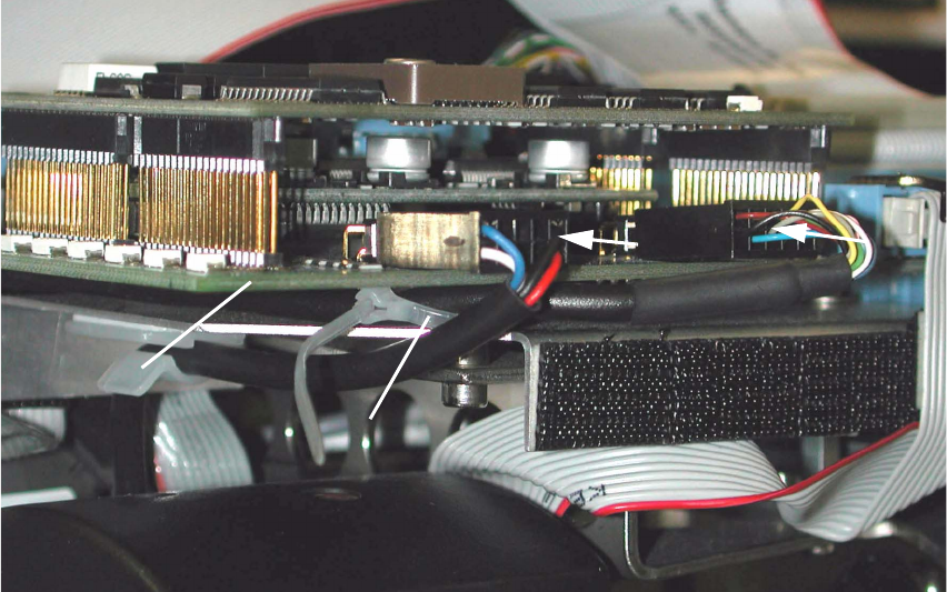
Abb. 2.6.6 HS-50, Modular Head PCB: Detail of Cable Fasteners and Plug-In Connector
Key:
1. Gantry head distributor HS-50, modular
2. Cable tie, fastener on spacer bolt
3. Plug-in connector of the component sensor cable
4. Plug-in connector of the round cable (motor/tachometer)
: Preshape the cable tie into an arch and thread it in around the spacer bolt (see Abb. 2.6.6 ->
2) located under the gantry head distributor, modular
: Run the component sensor cable under the PCB and back to the front, upstream of the spacer
bolt, and then out, as shown in Abb. 2.6.5 and Abb. 2.6.6.
: Make the plug-in connection of the component sensor cable on the gantry head distributor (see
Abb. 2.6.6 -> 3).
: Fasten the component sensor cable with cable tie to the spacer bolt (see Abb. 2.6.6 -> 2) in
such a manner that the strain on the plug-in connector is relieved but no large loop is created.
2
4
3
2
1
2 Assembly Instructions: Component Sensor (Option) for RV12-DLM1 Placement Head SIPLACE S-25 HM
2.6 Work Sequence 04/2007 Edition
42
: Restore the plug-in connection of the round cable (motor/tachometer) on the gantry head dis-
tributor. This cable is run outside around the component sensor, as shown in Abb. 2.6.6 -> 4.
: As the final step, make certain that both the plug-in connector and the cable entry fitting on the
component sensor are strain relieved.
2.6.4 S-25 HM: Laying the Component Cable Sensor, Plugging In the Connector
: As shown for HS-50 (see Abb. 2.6.5 -> 1 and 2), route the component sensor cable on S-25
HM up to the modular head PCB.
: Fasten it in the lower area of the placement head with the cable tie as shown in Abb. 2.6.5 ->
3). The cable entry fitting on the component sensor must be strain relieved.
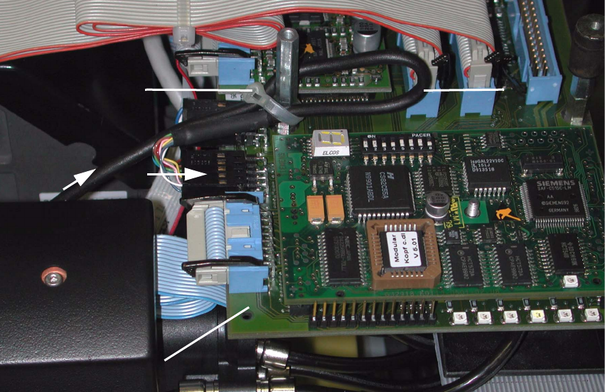
Abb. 2.6.7 S-25 HM, Modular Head PCB: Detail of Cable Fastening and Connector
Key:
1. Gantry head distributor (S-23) S-25 HM, modular
2. Plug-in connector on component sensor cable
3. Component sensor cable, loop
4. Cable tie, connection on spacer bolt
2
1
4
3