00193356-02.pdf - 第42页
2 Assembly Instructions: Component Sensor (Opti on) for RV12-DLM1 Placement Head SIPLACE S-25 HM 2.6 Work Sequence 04/2007 Edition 42 : Restore the plug-in connectio n of the round cable (motor/t achometer) on the gan tr…
SIPLACE S-25 HM 2 Assembly Instructions: Component Sensor (Option) for RV12-DLM1 Placement Head
04/2007 Edition 2.6 Work Sequence
41
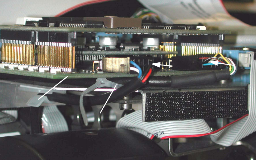
: Unplug the connector of the round cable (motor/tachometer) on the modular head PCB (see
Abb. 2.6.5 -> 5).
: Lay the component sensor cable upward toward the modular head PCB and fasten the cable
in the BOTTOM cable run on the placement head, as shown in Abb. 2.6.5 -> 2 and 3.
Abb. 2.6.6 HS-50, Modular Head PCB: Detail of Cable Fasteners and Plug-In Connector
Key:
1. Gantry head distributor HS-50, modular
2. Cable tie, fastener on spacer bolt
3. Plug-in connector of the component sensor cable
4. Plug-in connector of the round cable (motor/tachometer)
: Preshape the cable tie into an arch and thread it in around the spacer bolt (see Abb. 2.6.6 ->
2) located under the gantry head distributor, modular
: Run the component sensor cable under the PCB and back to the front, upstream of the spacer
bolt, and then out, as shown in Abb. 2.6.5 and Abb. 2.6.6.
: Make the plug-in connection of the component sensor cable on the gantry head distributor (see
Abb. 2.6.6 -> 3).
: Fasten the component sensor cable with cable tie to the spacer bolt (see Abb. 2.6.6 -> 2) in
such a manner that the strain on the plug-in connector is relieved but no large loop is created.
2
4
3
2
1
2 Assembly Instructions: Component Sensor (Option) for RV12-DLM1 Placement Head SIPLACE S-25 HM
2.6 Work Sequence 04/2007 Edition
42
: Restore the plug-in connection of the round cable (motor/tachometer) on the gantry head dis-
tributor. This cable is run outside around the component sensor, as shown in Abb. 2.6.6 -> 4.
: As the final step, make certain that both the plug-in connector and the cable entry fitting on the
component sensor are strain relieved.
2.6.4 S-25 HM: Laying the Component Cable Sensor, Plugging In the Connector
: As shown for HS-50 (see Abb. 2.6.5 -> 1 and 2), route the component sensor cable on S-25
HM up to the modular head PCB.
: Fasten it in the lower area of the placement head with the cable tie as shown in Abb. 2.6.5 ->
3). The cable entry fitting on the component sensor must be strain relieved.
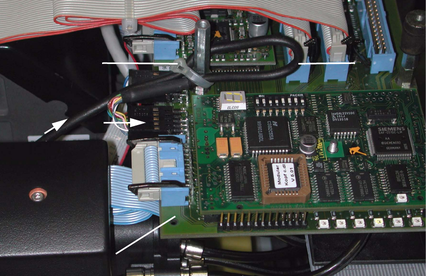
Abb. 2.6.7 S-25 HM, Modular Head PCB: Detail of Cable Fastening and Connector
Key:
1. Gantry head distributor (S-23) S-25 HM, modular
2. Plug-in connector on component sensor cable
3. Component sensor cable, loop
4. Cable tie, connection on spacer bolt
2
1
4
3
SIPLACE S-25 HM 2 Assembly Instructions: Component Sensor (Option) for RV12-DLM1 Placement Head
04/2007 Edition 2.6 Work Sequence
43
: Make the plug-in connection of the component sensor cable on the gantry head distributor S-
23 /S-25 HM (see Abb. 2.6.7 -> 1 and 2).
: Run the component sensor cable into a loop and fasten the cable to the spacer bolt with a cable
tie (see Abb. 2.6.7 -> 3 and 4).
The strain on the plug-in connector must be relieved.
2.6.5 Final Steps
: If present, mount the protective covers back on the placement head (5 socket hex head cap
screws M 3).
: Remove all of the tools, etc., from the machine’s working area.
: Hold the placement head by the handle and move it back into the area over the PCB conveyor.
-> While doing so, make certain that it stays at least the minimum distance away from the
X-gantry so that the crash proximity switch is not actuated.
: If present, fold the flap of the head crash protection unit back up.
: Now switch ON the compressed air supply at the main valve of the compressed air unit in the
machine base. Turn the machine ON.
Dock the mobile changeover table(s) so that the allocation is the same as it previously was.
: If present, fold down the head crash protection units.
2.6.6 Installing Software Version 503.xx on Line Computer and Station Computer
The SW V 503.xx is required on the line computer and the station computer in order to operate
the component sensor. 2
To install it, proceed as described in the pertinent software version description for 503.xx. The in-
structions are in the software package 503.xx (Item no.: see Section 1.4.2). 2
NOTE:
It is also possible to install the SW SIPLACE PRO on the line computer (see Section 1.4.2). 2