CM602规格说明书(英文).pdf - 第11页
CM602-L 2006.0515 - 6 - High Accuracy Placement ■ Newly-dev eloped compo nent thicknes s sensor (O pt ion * ) (To be r eleased i n Sept ember 2006) The ne wly-deve loped com ponen t thick ness sensor will im prove the pl…
CM602-L 2006.0515
- 5 -
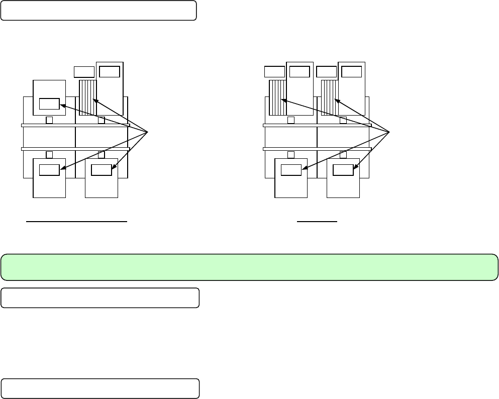
Direct tray feeder
The table connected with the direct tray feeder DT50S-20 (option) holds a maximum of 20 types of trays and of 6
types of feeders.
Type D-0, D-1 and E-0
Type F-0
Efficient Changeover
Multi job production
Per CM602-L, 216 types of components (on an 8 mm tape basis) can be set; when two or three machines are
coupled, the taped components to be placed on multiple types of PCBs can be set at a time.
The programming support system PS200-G has the feature that apportions the placement data to each stage,
taking the multi job production system like this into consideration.
Preparation while the machine is operating
■
Changing feeders during operation
It is possible to insert or extract the feeders that are not in use while the machine is operating.
That enables you to prepare for the next model during operation.
■
Feeder cart
The base where feeders will be set is integral with the feeder cart; therefore, it can easily be set or removed.
That enables you to set the feeders for the next model beforehand (Offline preparation).
Moreover, the removable feeder setting area that is integral with the changing cart will facilitate the mainte-
nance work.
* For High Speed head (12 nozzles) type, the version of the software incorporated in the feeder cart needs to be updated to Ver. 1.20 or
later. (Because of the gang feed support in right and left lanes of double tape feeder.)
■
Gang changing of support pins
In changeover, the PCB support pins need changing; however, CM602-L adopts the support pin block system.
Since setting the support pins can be performed with a support pin set jig, only you have to do for changeover
is removing and setting the block.
* About the support pin blocks
Common to CM402-L, CM401-L, and DT401-F.
Not sharable with CM402-M, CM401-M, CM400-M, DT401-M, DT400-M, CM212-M, CM202/201, and CM301.
6
2727
Feeder table
(Four places)
20 6 20
27
27
27
Feeder table
(Four places)
20
6

CM602-L 2006.0515
- 6 -
High Accuracy Placement
■
Newly-developed component thickness sensor (Option
*
)
(To be released in September 2006)
The newly-developed component thickness sensor will improve the placement quality, featuring component
thickness measurement (chip data entry), component bring-back check, and nozzle tip check.
* This is an option exclusive to High Speed head (12 nozzles) type.
■
High resolution camera and newly developed recognition system
Wide field and high resolution line camera recognizes minute components like 0603 (0201”) chips up to large
sized connectors with high accuracy. And the newly developed recognition system improves not only the
recognition accuracy but also the recognition speed. (As compared with our conventional machines
(CM402-L), especially the recognition speed against minute components has been improved. However, not
all the components’ recognition speed will not be improved.)
As for the placement accuracy, the High Speed head type has achieved ±50 µm (Cpk
≥
1) for 0603 and 1005;
the Multi-functional head type, ±35 µm (Cpk
≥
1) for QFP. We provide high level narrow adjacent placement.
■
Calibration feature
Reassessed calibration program provides high accuracy placement. Automatic calibration feature maintains
an initial high precision even during operation. (Each parameter is automatically corrected by periodically
recognizing the gauge mark during operation.)
■
High speed low vibration control
High speed low vibration control has been introduced to the XY unit operation.

CM602-L 2006.0515
- 7 -
3. Specification
3.1 Standard Specifications
Model: CM602-L
Electric source
・
Rated voltage 3-phase, AC 200/220 V ±10 V, AC 380/400/420/480 V ±20 V
・
Frequency 50 Hz/60 Hz
・
Power 4.0 kVA
・
Feeding specification For the case of AC 290 V or more (380 V or more tap), make
sure that the feeding side is in star (Y) connection and the volt-
age between the PE (protective earth) terminal and each phase
is AC 290 V or less.
Auxiliary elec-
tric source
(HUB electric
source : option)
・
Rated voltage 1-phase, AC 100 V to 240 V
・
Frequency 50 Hz/60 Hz
・
Power 140 VA
・
Feeding specification This electric source is required when the downstream equipment
communicates with PT while the main electric source of this
machine is OFF.
Pneumatic
source
・
Supply air pressure Min. 0.49 MPa to Max. 0.78 MPa
(Working air pressure: 0.49 MPa to 0.54 MPa)
・
Supply air amount 170 L/min [Normal]
(
*
)
・
Air consumption Max.: 170 L/min [Normal]
(
*
)
When using the following option, you need an extra air source.
・
8 L/min [Normal]
(
*
)
per intelligent bulk feeder
* [Normal] (ISO/DIS 5598)
Temperature: 20
℃
Absolute pressure: 101.3 kPa Relative humidity: 65 %
Dimensions
・
Main body only W 2 350 mm × D 2 690 mm × H 1 430 mm
(without 3-Color Signal Tower and Touch Panel)
・
DT50S-20 connected W 2 350 mm × D 2 765 mm × H 1 430 mm
(without 3-Color Signal Tower and Touch Panel)
Mass
・
Main body mass 3 400
㎏
・
Feeder cart mass 140
㎏
/1 set
・
DT50S-20 mass 195
㎏
/1 set (Option)
・
Standard structure mass 3 960
㎏
(One main body and four feeder carts)
Environment
・
Temperature 10
℃
to 35
℃
・
Humidity 25 %RH to 75 %RH [No condensation]
・
Altitude 1 000 m or less, above sea level
Operating unit
・
Interactive operation with LCD color touch panels
(Front side and rear side: Standard equipment)
One touch changeover between English and Japanese
(When Chinese is supported, Japanese/English/Chinese is selectable at the flick of a switch.)
Recognition screen display (Chip/PCB recognition screen is displayed in superimpose screen
(
*
)
with one touch of a button.)
Hierarchical operation (Operator/Engineer)
* Recognition screen is displayed on operating screen.
Paint color
・
Standard color White: W-13 (G50)
Control System
・
Microcomputer system (VxWORKS)
Full closed-loop system through the linear servomotors
[X, Y axes and Z axis (High Speed head (12 nozzles))]
Semi closed loop system through the AC servomotor
[Z axis (High Speed head (8 nozzles) and multi-functional head), θ axis,
rail width adjustment axis]
Command
System
・
Designation of X, Y, Z, and θ coordinates
Program
・
No. of NC Program Steps No limit (That depends on the PC’s hard-disk space of PT.)
No. of points per program: Max. 10 000 points/line
・
No. of Component Libraries No limit (That depends on the PC’s hard-disk space of PT.)
Standard library: 138 types for high speed head, 172 types
for multi-functional head
Others
・
Program Functions
See “5. Other Standard Functions.”
・
Data creation
Please refer to “PS200-G Specification” and “PT200-G Specification.”