CM602规格说明书(英文).pdf - 第18页
CM602-L 2006.0515 - 13 - 4.2 Nozzle Type & Configuration ■ Nozzles f or High Speed h ead (12 noz zles) All noz zles are o ptions as well as th e tape f eeders so that you can se lect t he best com bination of them to…
CM602-L 2006.0515
- 12 -
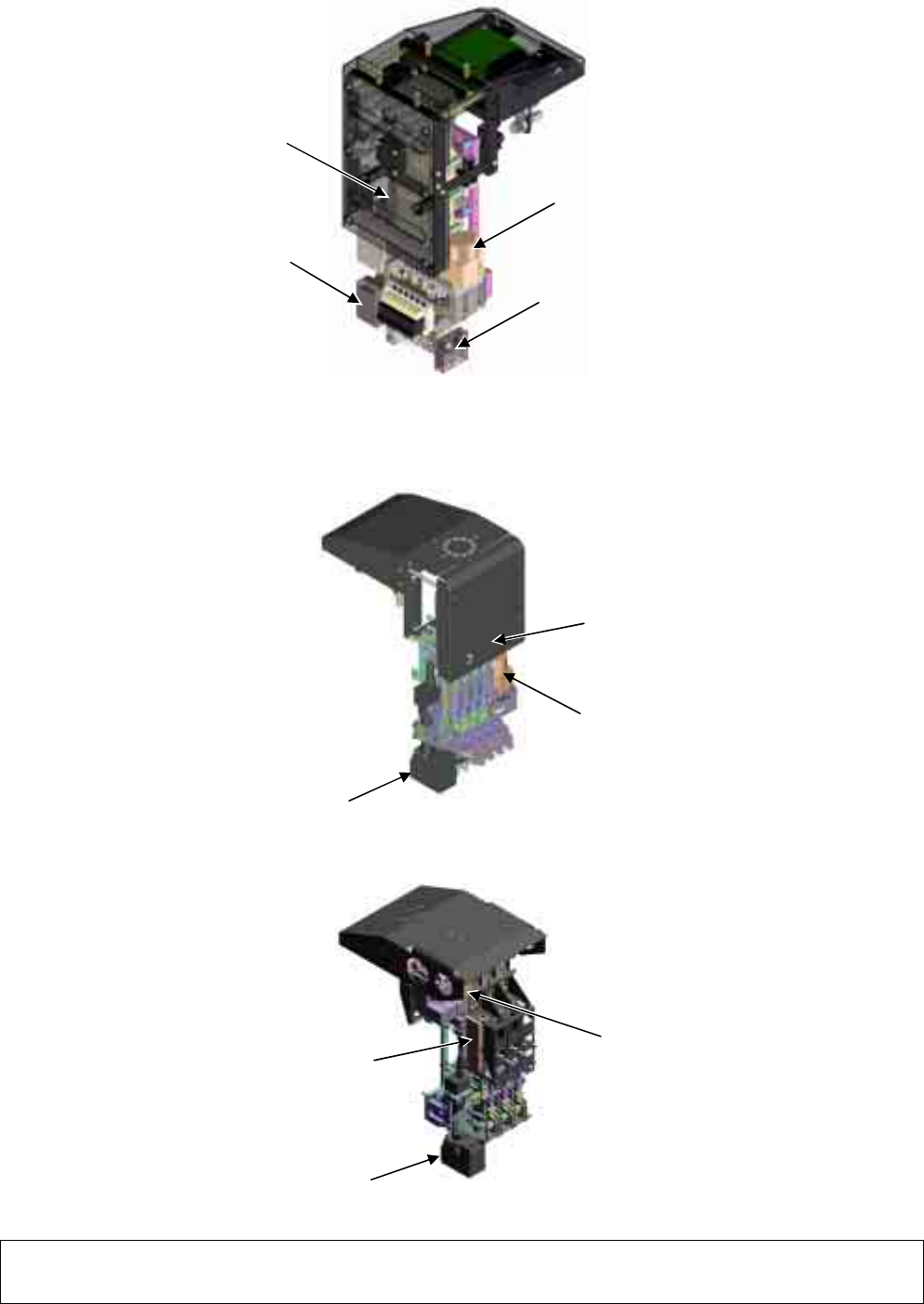
4.1 Head Configuration
■
High Speed head (12 nozzles) Unit Appearance and Parts Names
* For High Speed head (12 nozzles) type, the versions of the software incorporated in the double tape feeder and the feeder cart need to
be updated to Ver. 5.00 or later and Ver. 1.20 or later, respectively. (Because of the gang feed support in right and left lanes of double
tape feeder.)
■
High Speed head (8 nozzles) Unit Appearance and Parts Names
■
Multi-functional head Appearance and Parts Names
∗∗
Remarks
∗∗
•
Since the heads intended for the CM400 series may not be available, please contact us.
•
The “High Speed head (8 nozzles)” is identical with the “High Speed head” of CM400 series.
Motor for vertical motion (Z-axis)
Motor for rotary motion (
θ
-axis)
PCB Recognition Camera
Motor for vertical motion (Z-axis)
Motor for rotary motion (
θ
-axis)
PCB Recognition Camera
Component thickness sensor (option)
Motor for vertical motion (Z-axis)
PCB Recognition Camera
Motor for rotary motion (
θ
-axis)
CM602-L 2006.0515
- 13 -
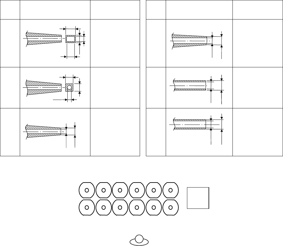
4.2 Nozzle Type & Configuration
■
Nozzles for High Speed head (12 nozzles)
All nozzles are options as well as the tape feeders so that you can select the best combination of them to
make full use of CM602-L to your production pattern.
No.
Shape
(All dimensions in mm)
Applicable
component
(Typical examples)
No.
Shape
(All dimensions in mm)
Applicable
component
(Typical examples)
205S
0603R, C 115S
1608R, C
2012R, C
SS-Mini Tr, Di
S-Mini Tr, Di
206S
0603R, C
1005R, C
120S
2012R, C
3216R, C
S-Mini Tr, Di
Mini Tr, Di
110S
1005R, C
1608R, C
130S
3225R, C
4532R, C
TAN-X
■
Nozzle layout for High Speed head (12 nozzles)
The layout and the maximum number of attachable nozzles for High Speed head (12 nozzles)
(The figures are seen from above.)
* Only the above six types of nozzles for High Speed head (12 nozzles) are available.
* Nozzles for High Speed head (8 nozzles) type are not available to the High Speed head (12 nozzles).
* In transmitting recognition, in some cases, component size and height are limited. (Because it is affected by the component shadow to
adjacent nozzles)
φ
1.8
φ
2.4
φ
0.7
φ
0.9
φ
0.9
φ
1.3
0.35
0.65
0.4
0.18
0.6
0.5
φ
0.3
φ
0.6
φ
0.5
12 nozzles
1 2 3 4
7 8 9
56
121110
PCB
recognition
camera
CM602-L 2006.0515
- 14 -
■
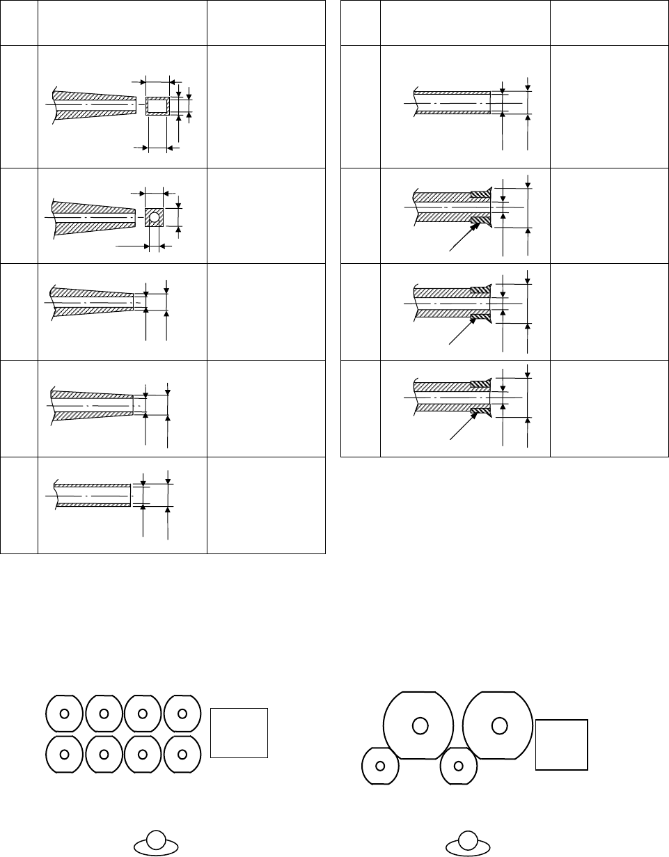
Nozzles for High Speed head (8 nozzles)
All nozzles are options as well as the tape feeders so that you can select the best combination of them to
make full use of CM602-L to your production pattern.
* These nozzles are shared with the CM400 series.
No.
Shape
(All dimensions in mm)
Applicable
component
(Typical examples)
No.
Shape
(All dimensions in mm)
Applicable
component
(Typical examples)
205
0603R, C
(0201” R, C)
130
3225R, C
(1210” R, C)
4532R, C
(1812” R, C)
TAN-X, B, C, D
Aluminum
electrolysis-
A, B, C
206
0603R, C
(0201” R, C)
1005R, C
(0402” R, C)
140
TAN-D
Aluminum
electrolysis-D
SOP, SOJ
PLCC, CSP
110
1005R, C
(0402” R, C)
1608R, C
(0603” R, C)
450
SOP, QFP
PLCC, BGA
to
18 mm × 18 mm
115
1608R, C
(0603” R, C)
2012R, C
(0805” R, C)
SS-Mini Tr, Di
S-Mini Tr, Di
460
SOP, QFP
PLCC, BGA
to
24 mm × 24 mm
120
2012R, C
(0805” R, C)
3216R, C
(1206” R, C)
S-Mini Tr, Di
Mini Tr, Di
■
Nozzle layout for High Speed head (8 nozzles)
The small nozzles (205, 110, 115, 120, 130, 140 described in above table) that support the components
measuring 12 mm or less diagonally can be attached to all the heads.
The large nozzles (450, 460 described in above table) that support the components exceeding 12 mm di-
agonally can be attached to the No.2 and the No.4 head. At this time, also the small nozzles can be attached
to the No.5 and the No.7 head.
The layout and the maximum number of attachable nozzles for High Speed head (8 nozzles)
(The figures are seen from above.)
* Nozzles for High Speed head (12 nozzles) type are not available to the High Speed head (8 nozzles).
φ
1.8
φ
2.4
φ
1.5
φ
6
Pad
φ
2.4
φ
10
Pad
φ
0.6
φ
0.5
φ
0.7
φ
0.9
0.6
0.5
φ
0.3
φ
0.9
φ
1.3
φ
1.5
φ
4
Pad
Eight small nozzles
1 2 3 4
5 6 7 8
PCB
recognition
camera
Two small nozzles
Two large nozzles
24
57
PCB
recognition
camera
0.35
0.65
0.4
0.18