CM602规格说明书(英文).pdf - 第26页
CM602-L 2006.0515 - 21 - ■ Recognition conditions of QFP Placem ent con ditio ns of Q FP are as follo ws. (Basical ly, placem ent Q FP is det erm ined and ex perim ented af ter gettin g the sam ple of it, and t hen it is…
CM602-L 2006.0515
- 20 -
4.3 Recognition Unit Configuration
■
Line Camera
The position in picking up the chip and the angle deviation are corrected with the image of line camera.
In addition, the presence of solder bumps can be detected
(*)
for BGA/CSP through the side lighting (option).
* There are limitations on the chips for which the bump detecting feature is available.
Please see the items describing the recognition condition of BGA.
Recognition
method
Recognition
speed
Applicable Component
Low
Components with leads of 0.5 mm or less pitch, and CSP.
Middle
BGA and 0603 (0201”) chip.
Chip with leads of the pitch between 0.5 mm and 0.8 mm.
Batch
recognition
High
General chip components including the square chips measuring 1005
(0402”) or over.
■
Lead Checker (Option)
Floating leads are detected by laser scanning all the leads of SOP, QFP, etc. whose size is 50 mm × 50 mm
or less.
・
Measurable range of the floating lead is up to ±0.75 mm.
・
Lead opening must be 0.2 mm or over to be detected.
・
Lower plane of the lead must be 0.2 mm or over to be detected.
・
Some leads cannot be laser scanned depending on the state of the leads’ bottom.
So please consult us before adopting this option.
■
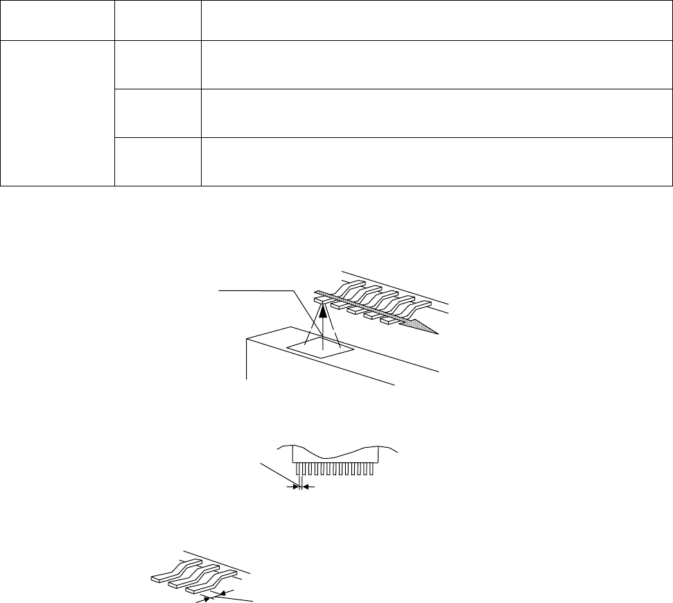
PCB Recognition Camera
・
Visual field: 5 mm × 5 mm
(For information about the dimensions of PCB recognition mark, see “6. PCB Design Standards.”)
Lead checke
r
Laser light
Opening is 0.2 mm or over.
Lower plane of the lead is 0.2 mm or over.
CM602-L 2006.0515
- 21 -
■
Recognition conditions of QFP
Placement conditions of QFP are as follows.
(Basically, placement QFP is determined and experimented after getting the sample of it, and then it is
judged to be placed or not.)
High Speed head (8 nozzles) Multi-functional head
Outside dimensions 5 mm × 5 mm to 24 mm × 24 mm 5 mm × 5 mm to 45 mm × 45 mm
Thickness 1.0 mm to 6.5 mm 1.0 mm to 21 mm
Lead pitch 0.65 mm, 1.0 mm, 1.27 mm, 1.5 mm
0.4 mm, 0.5 mm, 0.65 mm,
1.0 mm, 1.27 mm, 1.5 mm
Lead width 0.2 mm or over
Lead shape Leads must be protruding out of the mold area by 1 mm or over.
・
Feeding type
Fed by tape.
Fed by tray (supported by the shuttle tray feeder (option) or the direct tray feeder (option)).
* For information about the components that are not conforming to the above specifications, please consult us.
■
Recognition conditions of BGA
Placement conditions of BGA are as follows.
(Basically, placement BGA is determined and experimented after getting the sample of it, and then it is judged
to be placed or not.)
High Speed head (8 nozzles) Multi-functional head
Outside dimensions 7 mm × 7 mm to 24 mm × 24 mm 7 mm × 7 mm to 45 mm × 45 mm
Thickness 1.0 mm to 6.5 mm 1.0 mm to 21 mm
Bump pitch 1.0 mm, 1.27 mm, 1.5 mm
Bump diameter
φ
0.5 mm,
φ
0.7 mm,
φ
0.9 mm
Bump shape Globular, cylindrical, or lead form
Materials of bump High temperature solder, eutectic solder, 42 alloy lead
Number of bumps Matrix of Min. 3 × 3 to Max. 50 × 50
Arrangement of
bump
The pitch and dimensions of bump shall be consistent.
The bump missing and the staggered pattern are the same as those defined by
JEDEC and EIAJ regarding BGA.
・
To enable the simultaneous recognition of BGA appearance and solder balls, the body shall be made of
the glass epoxy. The recognition depends on the conditions of the placement surface of solder balls (pat-
tern, with or without through hall, luster, etc.).
・
BGA which is made of ceramic and has the gold body is placed with only the contour recognition.
・
Surface of bump
The surface of bump should be free from the blur due to oxidation.
(It needs to be checked whether to recognize or not, according to the condition of oxidation.)
・
Feeding type
Fed by tape.
Fed by tray (supported by the shuttle tray feeder (option) or the direct tray feeder (option)).

CM602-L 2006.0515
- 22 -
■
Recognition conditions of CSP
Placement conditions of CSP are as follows.
(Basically, placement CSP is determined and experimented after getting the sample of it, and then it is judged
to be placed or not.)
High Speed head (8 nozzles) Multi-functional head
Outside dimensions 5 mm × 5 mm to 24 mm × 24 mm 5 mm × 5 mm to 24 mm × 24 mm
Thickness 1.0 mm to 6.5 mm 1.0 mm to 21 mm
Bump pitch 0.5 mm to 1.0 mm
Bump diameter
φ
0.25 mm to
φ
0.7 mm
Bump shape Globular, cylindrical, or lead form
Materials of bump High temperature solder, eutectic solder, 42 alloy lead
Maximum bump
count
2 500
In positive grid arrangement, number of rows on most outer regions × number of columns is 50 × 50
In staggered arrangement, number of rows on most outer regions × number of columns is 25 × 25
Minimum bump
count
9
In positive grid arrangement, number of rows on most outer regions × number of columns is 3 × 3
In staggered arrangement, number of rows on most outer regions × number of columns is 3 × 3
Arrangement
of bump
The pitch and dimensions of bump shall be consistent.
(The bump missing and the staggered pattern are the same as those defined by
JEDEC and EIAJ regarding CSP.)
・
To enable the simultaneous recognition of CSP appearance and solder balls, the body shall be made of
the glass epoxy. The recognition depends on the conditions of the placement surface of solder balls (pat-
tern, with or without through hall, luster, etc.).
・
CSP which is made of ceramic and has the gold body is placed with only the contour recognition.
・
Surface of bump
The surface of bump should be free from the blur due to oxidation.
(It needs to be checked whether to recognize or not, according to the condition of oxidation.)
・
Feeding type
Fed by tape.
Fed by tray (supported by the shuttle tray feeder (option) or the direct tray feeder (option)).
■
Recognition conditions of Connector
The general conditions of placement connectors are as follows.
(Basically, placement connector is determined and experimented after getting the sample of it, and then it is
judged to be placed or not.)
High Speed head (8 nozzles) Multi-functional head
Outside dimensions 24 mm × 24 mm or less L 100 mm or less × W 90 mm or less (*)
Lead pitch 0.65 mm or over 0.5 mm or over
Lead width 0.2 mm or over
Lead shape Leads must be protruding out of the body by 1 mm or over.
Other shape
No through holes around contact pins shall exist in a vertical direction.
Contact pins shall not be exposed to the underside.
・
Feeding type
Fed by tape.
Fed by tray (supported by the shuttle tray feeder (option) or the direct tray feeder (option)).
Fed by stick (supported by the optional stick feeder).
* In the case of the placement of large sized connectors with the Multi-functional head, in addition to those, some limitations may be
imposed on the dimensions depending on the relation between the pick up position and the recognition range. For further information,
please contact us.