CM602规格说明书(英文).pdf - 第33页
CM602-L 2006.0515 - 28 - Tray Conditions ・ Tra y dimensions : The outs ide dim ensions of tra y shall satisf y the follo wing co nditi ons. * Up t o 25 mm thickness trays can be s pecially support ed. Please let us know …
CM602-L 2006.0515
- 27 -
■
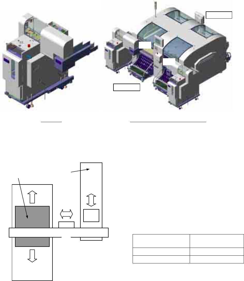
Shuttle Tray Feeder
ST40S-20 (Option)
Installing the shuttle tray feeder ST40S-20 onto CM602-L enables the placement of tray feeding components.
ST40S-20 can be installed on the rear side (AR and BR) of CM602-L. It cannot be installed on the front side
(AF and BF). The shuttle tray feeder can be connected only to the stage of multi-functional head type.
ST40S-20 is composed of the following three units. The unit
①
stores and selects trays, the unit
②
sends
components to the head of CM602-L, and the unit
③
acts as a bridge between these two units.
The unit
③
is placed on the top of the unit
①
that is self standing at the rear side of CM602-L.
The unit
②
is installed on the feeder cart of
CM602-L. Since there are no mechanical joints
between the units
②
and
③
, the feeder cart
can be detached or attached with ST40S-20 in-
stalled.
Please note that the unit
②
will occupy the slots
on the feeder cart. The number of slots to be
occupied is shown below.
Setting position
Number of slots
to be occupied
AR table 8
BR table 6
Since the unit
③
has two pick up heads that are raised and lowered by the air cylinder, two chips
(38 mm × 38 mm or under) can be transferred at a time.
The moving section of the unit
②
has two pick up sections equipped with the vacuum suction pads, pre-
venting chips from deviation while the components received from the unit
③
are transferred to the pick up
position of CM602-L.
①
②
③
CM602-L
pick up position
Tray
Rear side
Front side
BR
AR
Two ST40S-20 installed on CM602-L
∗
This illustration shows the machine with which two shuttle
tray feeders are connected. It is also possible to connect
only one shuttle tray feeder.
ST40S-20
CM602-L 2006.0515
- 28 -
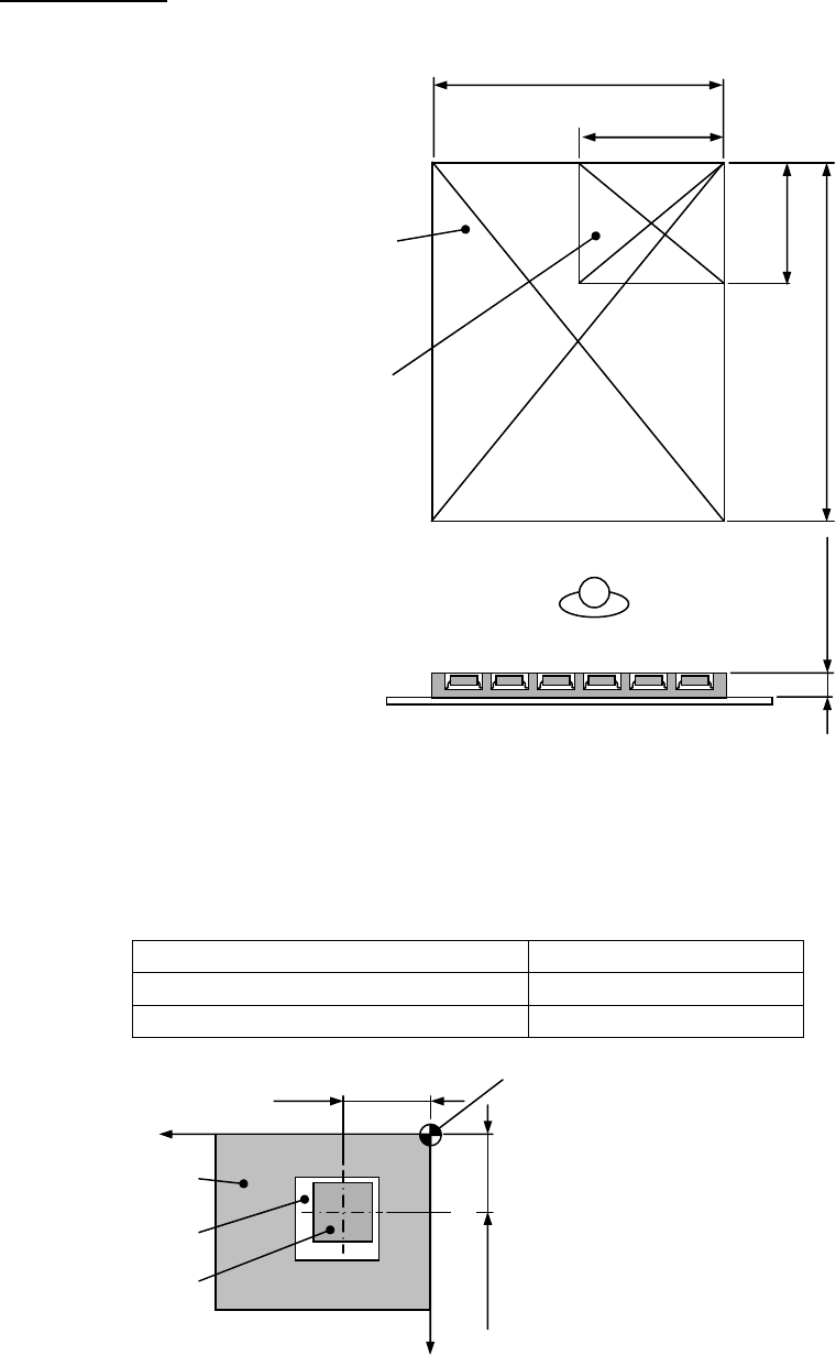
Tray Conditions
・
Tray dimensions: The outside dimensions of tray shall satisfy the following conditions.
* Up to 25 mm thickness trays can be specially supported.
Please let us know your desired one when placing an order because it cannot be supported after delivery.
・
Component holding: Tray shall be capable of holding components, satisfying the following conditions.
Conditions of component Position error
Pick up face: Under 10 mm × 10 mm ±1.0 mm or less
Pick up face: 10 mm × 10 mm or over ±1.5 mm or less
* However, these conditions are valid only when the top of component has a flat pick up face.
Maximum tray dimensions
Max. 230 mm
Min. 100 mm
Min. 85 mm
Max. 330 mm
Min. 2 mm
Max. 11 mm
Minimum tray dimensions
Xw + Position erro
r
Yw + Position erro
r
Tray setting reference point
(Tray origin)
Coordinates of component’s cente
r
(X, Y) = (Xw, Yw)
Tray
Pocket
Component
X
Y
CM602-L 2006.0515
- 29 -
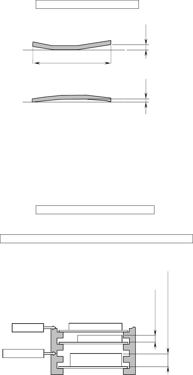
・
Warp: “Warp” of the tray to be loaded on a pallet shall meet the following conditions.
“
Warp” = Clearance Max. 0.5 mm
・
Type: For enough strength and dimensional accuracy, tray shall be injection molded, not vacuum molded.
(If your trays do not meet these conditions, please consult us. Then we check your sample trays and
suggest option or customization.)
・
Conditions for tray loading: The trays (components) to be loaded on a pallet and a magazine shall satisfy
the following conditions.
①
The total mass of components on a tray shall be 2
㎏
or less including the tray.
(Excluding the mass of pallet)
②
The total mass of the magazine with pallets and trays (components) shall be 20
㎏
or less.
Magazine + Pallets + Trays + Components = Max. 20
㎏
/magazine
③
If the height of the tray on a pallet exceeds 11 mm, a pallet cannot be inserted into the next higher slot
in the magazine.
Tray + Components = Max. 2
㎏
/pallet
Not insertable
Over 11 mm to 25 mm or less
11 mm or less
Insertable
Clearance
Tray
Clearance
Tray
Max. 330 mm