CM602规格说明书(英文).pdf - 第34页
CM602-L 2006.0515 - 29 - ・ W arp: “W arp” of the tra y to be load ed on a pallet s hall meet the f ollowin g con ditions . “ W a rp” = Clear ance Max . 0 .5 mm ・ T y pe: For enough s trength and dim ensiona l accur ac y,…
CM602-L 2006.0515
- 28 -
Tray Conditions
・
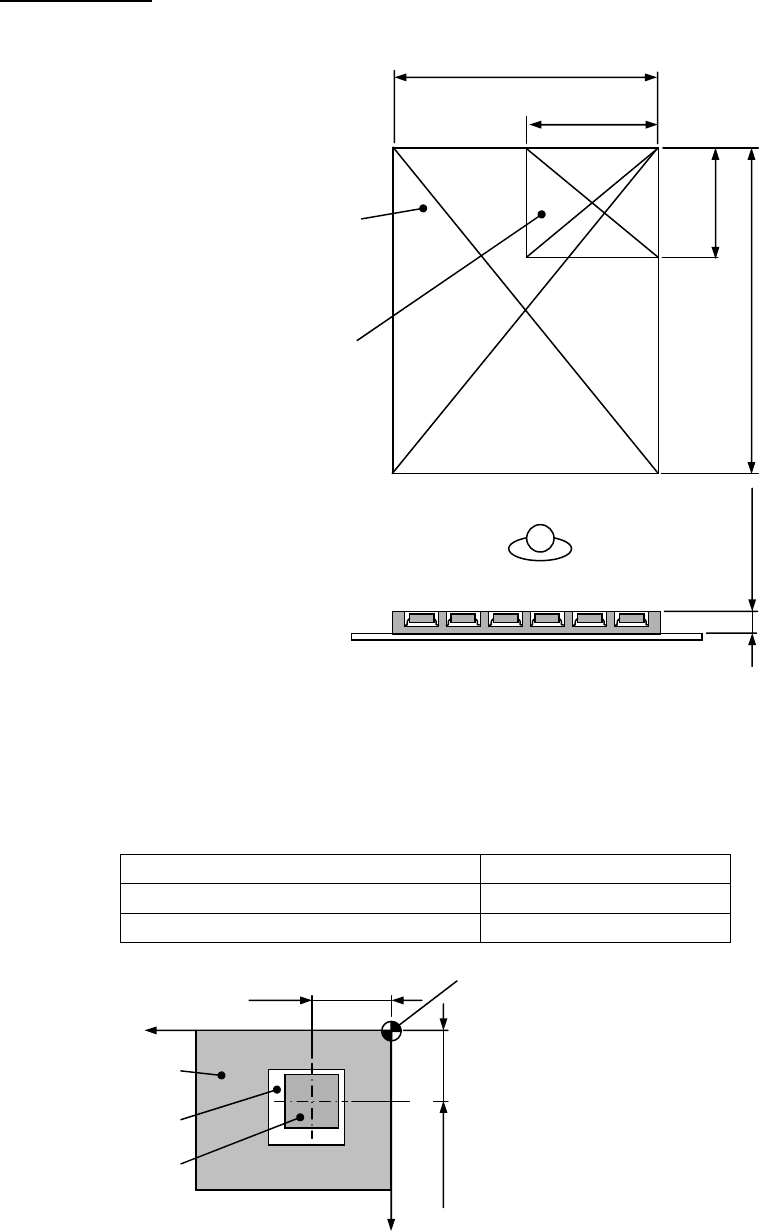
Tray dimensions: The outside dimensions of tray shall satisfy the following conditions.
* Up to 25 mm thickness trays can be specially supported.
Please let us know your desired one when placing an order because it cannot be supported after delivery.
・
Component holding: Tray shall be capable of holding components, satisfying the following conditions.
Conditions of component Position error
Pick up face: Under 10 mm × 10 mm ±1.0 mm or less
Pick up face: 10 mm × 10 mm or over ±1.5 mm or less
* However, these conditions are valid only when the top of component has a flat pick up face.
Maximum tray dimensions
Max. 230 mm
Min. 100 mm
Min. 85 mm
Max. 330 mm
Min. 2 mm
Max. 11 mm
Minimum tray dimensions
Xw + Position erro
r
Yw + Position erro
r
Tray setting reference point
(Tray origin)
Coordinates of component’s cente
r
(X, Y) = (Xw, Yw)
Tray
Pocket
Component
X
Y
CM602-L 2006.0515
- 29 -
・
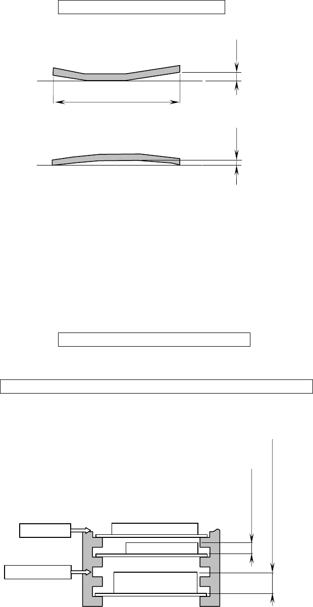
Warp: “Warp” of the tray to be loaded on a pallet shall meet the following conditions.
“
Warp” = Clearance Max. 0.5 mm
・
Type: For enough strength and dimensional accuracy, tray shall be injection molded, not vacuum molded.
(If your trays do not meet these conditions, please consult us. Then we check your sample trays and
suggest option or customization.)
・
Conditions for tray loading: The trays (components) to be loaded on a pallet and a magazine shall satisfy
the following conditions.
①
The total mass of components on a tray shall be 2
㎏
or less including the tray.
(Excluding the mass of pallet)
②
The total mass of the magazine with pallets and trays (components) shall be 20
㎏
or less.
Magazine + Pallets + Trays + Components = Max. 20
㎏
/magazine
③
If the height of the tray on a pallet exceeds 11 mm, a pallet cannot be inserted into the next higher slot
in the magazine.
Tray + Components = Max. 2
㎏
/pallet
Not insertable
Over 11 mm to 25 mm or less
11 mm or less
Insertable
Clearance
Tray
Clearance
Tray
Max. 330 mm
CM602-L 2006.0515
- 30 -
Conditions of Component
The components meeting all the following conditions (
①
to
⑦
) can be fed by the shuttle tray feeder.
①
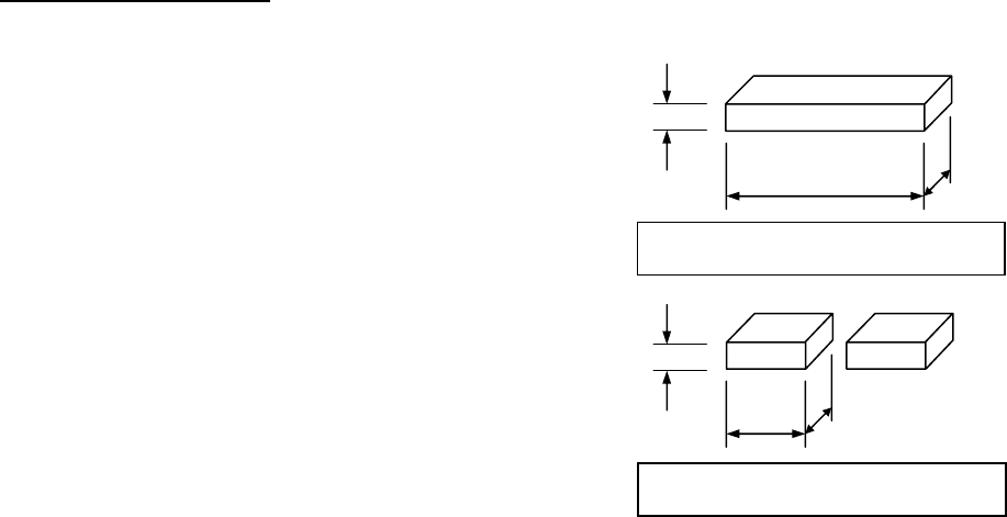
Outside dimensions of component
The outside dimensions of component shall be
L : 100 mm or less
W : 90 mm or less
T : 10 mm or less
For pick up and transfer by two heads
L : 38 mm or less
W : 38 mm or less
T : 10 mm or less
②
Mass of component
The mass of component shall be 30
g
or less.
③
The center of the component’s outside dimensions shall conform to its barycenter.
④
The barycenter position on the top of the component shall have a
φ
9 mm or more flat pick up face al-
lowing a stable pick up.
(In using the standard accessory
φ
6 pad nozzle)
⑤
In placement, the projection to be projected below the top of PCB shall not exist on the underside of the
component, which can be stably placed on a plane without tilting, shaking, and rolling.
⑥
The components shall be in the tray that meets its conditions.
⑦
Standard available components
(1) SOP 9 mm × 15 mm to 9 mm × 18 mm
(2) QFP 12 mm × 12 mm to 53 mm × 53 mm
(3) SOJ 11 mm × 21 mm to 11 mm × 26 mm
(4) PLCC 12 mm × 12 mm to 30 mm × 30 mm
(5) BGA 9 mm × 9 mm to 45 mm × 45 mm
(6) CSP 9 mm × 9 mm to 24 mm × 24 mm
* Except for the components mentioned above samples are required in advance to investigate the possibility of
placement.
Maximum dimensions and mass for
single component transport
100 mm
90 mm
10 mm
30
g
30
g
10 mm
38 mm
38 mm
Maximum dimensions and mass for
double component transport