CM602规格说明书(英文).pdf - 第39页
CM602-L 2006.0515 - 34 - ・ W arp: “W arp” of the tra y to be load ed on a pallet s hall meet the f ollowin g con ditions . “ W a rp” = Clear ance Max . 0 .5 mm ・ T y pe: For enough s trength and dim ensiona l accur ac y,…
CM602-L 2006.0515
- 33 -
Tray Conditions
・
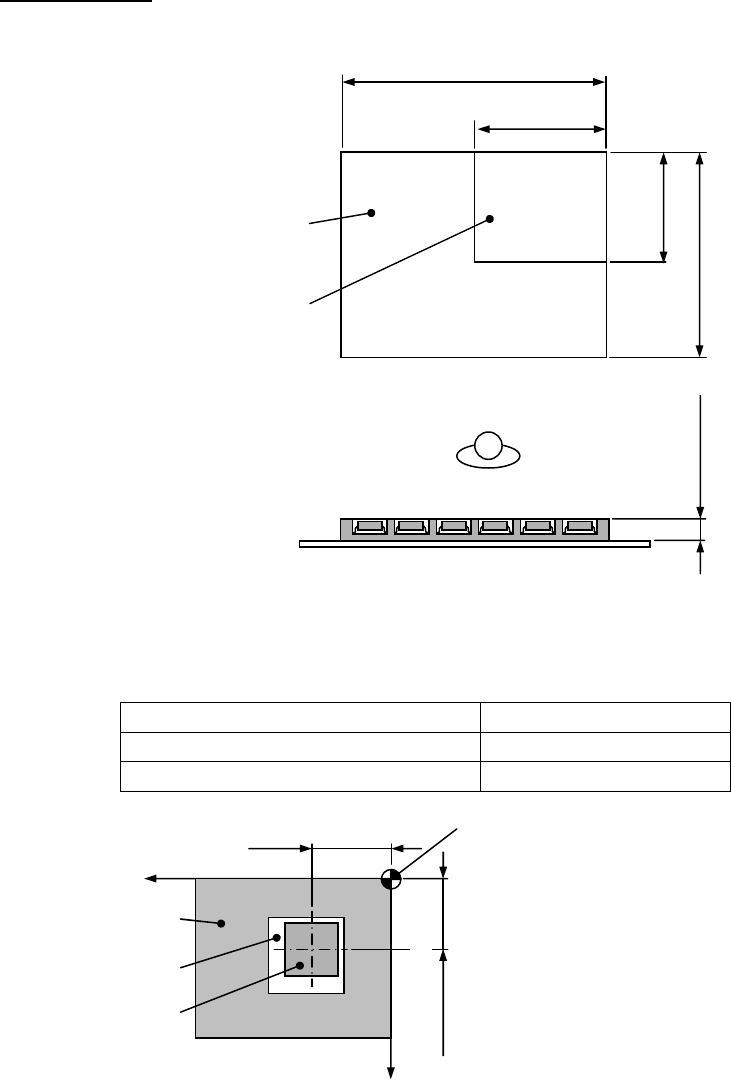
Tray dimensions: The outside dimensions of tray shall satisfy the following conditions.
・
Component holding: Tray shall be capable of holding components, satisfying the following conditions.
Conditions of component Position error
Pick up face: Under 10 mm × 10 mm ±1.0 mm or less
Pick up face: 10 mm × 10 mm or over ±1.5 mm or less
* However, these conditions are valid only when the top of component has a flat pick up face.
Xw + Position erro
r
Yw + Position error
Tray setting reference point
(Tray origin)
Coordinates of component’s cente
r
(X, Y) = (Xw, Yw)
Tray
Pocket
Component
X
Y
Maximum tray dimensions
Minimum tray dimensions
Max. 335 mm
Min. 100 mm
Min. 85 mm
Max. 136 mm
CM602-L 2006.0515
- 34 -
・
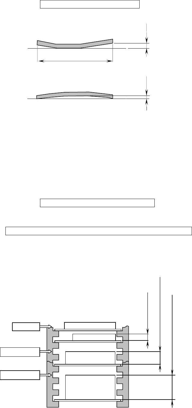
Warp: “Warp” of the tray to be loaded on a pallet shall meet the following conditions.
“
Warp” = Clearance Max. 0.5 mm
・
Type: For enough strength and dimensional accuracy, tray shall be injection molded, not vacuum molded.
(If your trays do not meet these conditions, please consult us. Then we check your sample trays and
suggest option or customization.)
・
Conditions for tray loading: The trays (components) to be loaded on a pallet and a magazine shall satisfy
the following conditions.
①
The total mass of components on a tray shall be 1
㎏
or less including the tray.
(Excluding the mass of pallet)
②
The total mass of the magazine with pallets and trays (components) shall be 20
㎏
or less.
Magazine + Pallets + Trays + Components = Max. 20
㎏
/magazine
③
If the height of the tray on a pallet exceeds 11 mm, a pallet cannot be inserted into the next higher slot
in the magazine.
Additionally if the height of the tray on a pallet exceeds 26 mm, a pallet cannot be inserted into the next
higher slot in the magazine.
Tray + Components = Max. 1
㎏
/pallet
Clearance
Tray
Clearance
Tray
Max. 335 mm
Over 11 mm to 26 mm or less
11 mm or less
Insertable
Over 26 mm to 33 mm or less
Not insertable
Not insertable
CM602-L 2006.0515
- 35 -
5. Other Standard Functions
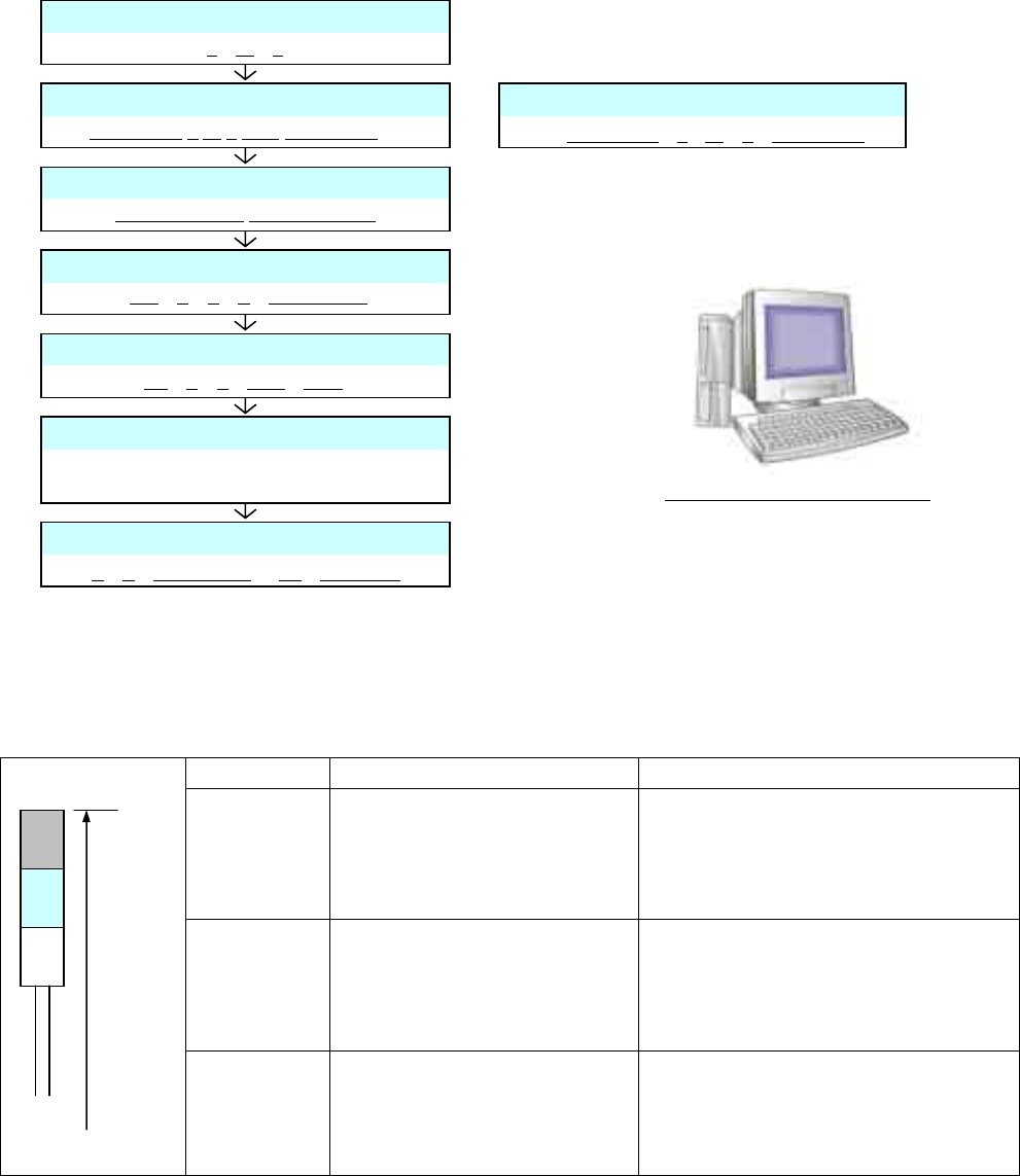
5.1 Programming Functions
All data are created on PT200-G, the data creating device. Some data, however, can be modified on the machine.
The data modified on the machine and what was taught are fed back to PT200-G automatically. Any of the four
corners of PCB can accept the origin of coordinate data.
PS200-G will make data creation more efficient; for example, it distributes data taking the multi-job production
system into consideration.
* As for the hardware for PT200-G, prepare by yourself.
Refer to the separate volume, “PT200-G Specification” for details of PT200-G.
Refer to the separate volume, “PS200-G Specification” for details of PS200-G.
5.2 3-Color Signal Tower
Color of signal tower and lighting standard
Signal Color Classification Lighting Standard
Red Emergency stop error
・
Trouble in shafts of motors
・
Drop in air pressure
・
Trouble in PCB supports
・
Head trouble
・
Tape trouble
Yellow Single stop error
・
Pickup error
・
Placement error
・
PCB transfer error
・
No works
・
Nozzle change error
Green
In operation
Electric source ON
(e.g., in automatic operation)
(This, however, is off while red or yel-
low is blinking.)
* Lighting specifications are programmable.
Data creating software PT200-G
PC board Data
L
W
T
Parts Data
Chip Name
L W T REF Style Angle …
Tray Data
Tray Name
L
W
T
Chip Count
Fixation Information
Feeder Fixation
Nozzle Fixation
Max. 10 000
p
oints
Block Data
No.
X
Y
A
Parts Name
Block Attribute Data
BL
X
Y
BAD
ROT
Feeder Arrangement
Nozzle Arrangement
Max. 10 000 points
Placement Data
X
Y
Parts Name
BL Comment
2 000 mm
from floor
(Standard)
Green
Yellow
Red