CM602规格说明书(英文).pdf - 第48页
CM602-L 2006.0515 - 43 - A-1 To s et the PCB tr ansfer line heigh t at 930 mm above the f loor. Fact ory Support f or 930 m m transfer lin e ・ The s tandard hei ght of the PCB trans fer li ne is 900 m m above t he flo or…
CM602-L 2006.0515
- 42 -
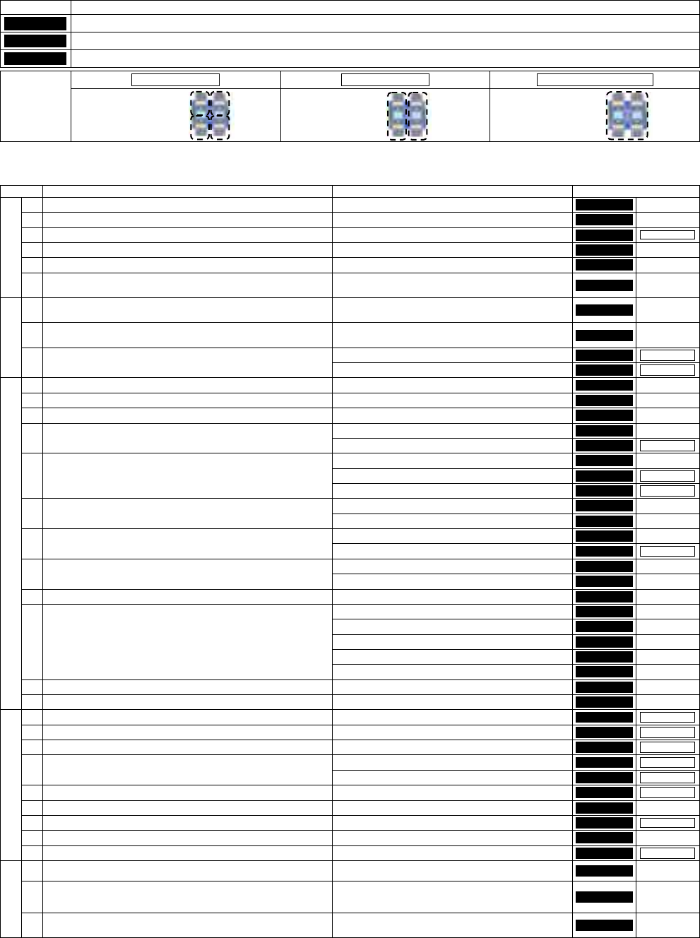
8. Options
Options are classified as follows.
Category Description
Factory
These options need to be supported when the machine is being manufactured before shipment.
On-site
These options can be added after the machine has been delivered. However, a construction work is required on the spot.
Customer
These options can be added after the machine has been delivered. A construction work on the spot is not required.
By table By stage Whole machine
Category
Can be supported
for each table.
Can be supported
for each stage.
Supported as
a whole of machine.
*
Depending on user’s machine specification, the manufacturing No., etc., some options may not fit the above classification.
For details, please consult us before purchasing the machine.
Please select options which answer customer/s purposes.
No. Purpose / Feature Option name Category
1
To set the PCB transfer line height at 930 mm above the floor. ・
Support for 930 mm transfer line
Factory
-
2
To set the PCB transfer line height at 950 mm above the floor. ・
Support for 950 mm transfer line
Factory
-
3
To transfer PCB. ・
PCB conveyor
(*1)
Factory
Whole machine
4
To set shuttle tray feeder. ・
Extension conveyor for shuttle tray feeder
Factory
-
5
To get space after the upstream machine. ・
Upstream extension conveyor
Factory
-
A
6
To provide the post placement standby area for the transfer
downmost stream area.
・
Downstream extension conveyor
Factory
-
1
To change the positions of PCB support pins externally, in
order to reduce the changeover time.
・
PCB support block
Customer
-
2
To set up the positions of support pins for new PCB externally,
in order to reduce the changeover time.
・
Support pin setting jig
Customer
-
・
Nozzle changer (for High Speed head (12 nozzles))
(*3)
On-site
By stage
B
3
To automate the nozzle changing operation in changeover.
・
Nozzle changer (for High Speed head (8 nozzles))
(*2)
On-site
By stage
1
To select the nozzle to the production pattern. ・
Nozzle
Customer
-
2
To store nozzles. ・
Nozzle case
Customer
-
3
To select the tape feeder to the production pattern. ・
Tape feeder
Customer
-
・
32 mm adhesive tape feeder
Customer
-
4
To use the 32 mm adhesive tape.
・
Air supply unit for the feeder
Factory
By table
・
Tape feeder (boss of 21 mm deep maximum)
Customer
-
・
Cutting unit for 21 mm thickness T/F (adapter)
On-site
By table
5
To use the tape feeder of 21 mm deep.
・
Feeder cart for 21 mm thickness T/F (adapter)
On-site
By table
・
Intelligent stick feeder
Customer
-
6
To select the stick feeder according to the production pattern.
・
Guide block
Customer
-
・
Intelligent bulk feeder
Customer
-
7
To select the bulk feeder according to the production pattern.
・
Air supply unit for the feeder
Factory
By table
・
Feeder cart
Customer
-
8
To prepare feeders externally.
・
Cart stand box (Electric source box)
Customer
-
9
To manage and store tape feeders. ・
Tape feeder stand
Customer
-
・
Shuttle tray feeder ST40S-20
On-site
-
・
Shuttle tray feeder installation ready
Factory
-
・
Direct tray feeder DT50S-20
On-site
-
・
Direct tray feeder installation ready
Factory
-
10
To place tray feeding components.
・
6-row feeder base mount
Factory
-
11
To improve the workability of tape splicing. ・
Splicing cart
Customer
-
C
12
To maintenance the Intelligent feeder. ・
Intelligent Feeder Check Unit
Customer
-
1
To place BGA, CSP. ・
Side lighting
On-site
By table
2
To detect the floating leads of SOP, QFP etc. ・
Lead checker
(*4)
On-site
By table
3
To align and eject the NG components onto the conveyor. ・
NG-components ejection conveyor
(*4)
Customer
By table
・
High Speed head (12 nozzles)
On-site
By stage
4
To replace with High Speed head (8 nozzles) or High Speed
head (12 nozzles).
・
High Speed head (8 nozzles)
On-site
By stage
5
To replace with Multi-functional head. ・
Multi-functional head (including the nozzle changer)
(*5)
On-site
By stage
6
To manage and store the removed heads. ・
Head stand
Customer
-
7
To place components onto ceramic PCB. ・
Ceramic board support
On-site
Whole machine
8
To use the parts verify function. ・
Pana PRO/CVT supporting unit
Factory
-
D
9
To detect the components brought back. ・
Component thickness sensor
(*6)
On-site
By stage
1
Required for the regular maintenance. ・
Lubrication set
・
Maintenance jig
Customer
-
2
Required for adjustments.
・
Adjustment jig
・
Plane calibration jig
・
Placement load measuring jig
(*4)
Customer
-
E
3
To enable the communication between PT and only the desired
machine with its power ON.
・
HUB power supply box
Factory
-
*1: Please be sure to select the PCB conveyor.
*2: These options can be installed exclusively on the stage for which the High Speed head (8 nozzles) is selected.
*3: These options can be installed exclusively on the stage for which the High Speed head (12 nozzles) is selected.
*4: These options can be installed exclusively on the stage for which the Multi-functional head is selected.
*5: Nozzle changer (for the Multi-functional head) is included with the Multi-functional head.
*6: It is an option only for a High Speed head (12 nozzles).
CM602-L 2006.0515
- 43 -
A-1
To set the PCB transfer line height at 930 mm above the floor.
Factory
Support for 930 mm transfer line
・
The standard height of the PCB transfer line is 900 mm above the floor.
A-2
To set the PCB transfer line height at 950 mm above the floor.
Factory
Support for 950 mm transfer line
・
The standard height of the PCB transfer line is 900 mm above the floor.
A-3
To transfer PCB.
(Please be sure to select)
Factory
Whole machine
PCB conveyor
・
This is a single lane conveyor that transfers PCBs and fixes them at each stop position.
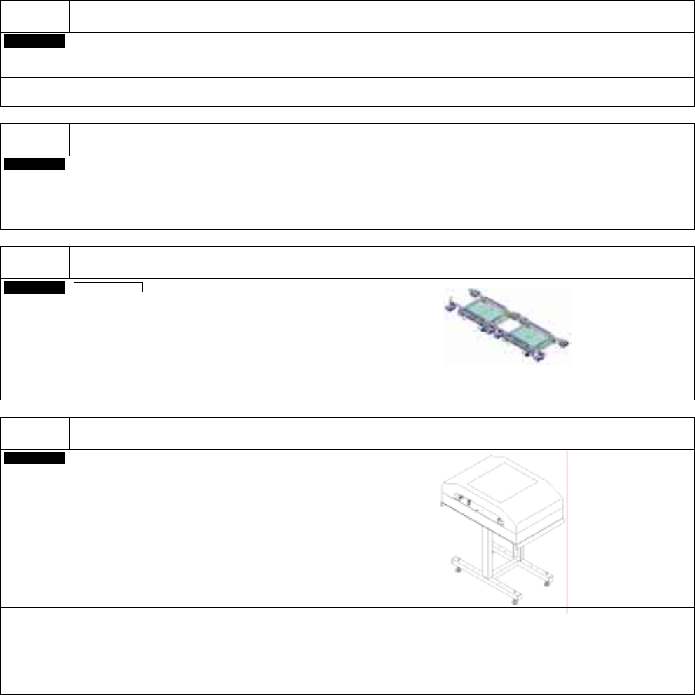
A-4
To set shuttle tray feeder.
Factory
Extension conveyor for shuttle tray feeder
・
When installing the shuttle tray feeders, you are recommended to install the extension conveyor (supporting shuttle
trays), however, also the combination of upstream conveyor and downstream conveyor is available.
(This extension conveyor can be inserted between upstream extension conveyor and downstream extension conveyor.
Doing so provides space between the upstream and downstream processes.)
・
“Shuttle tray feeder installation ready” needs to be selected.
+20
-0
+20
-0
CM602-L 2006.0515
- 44 -
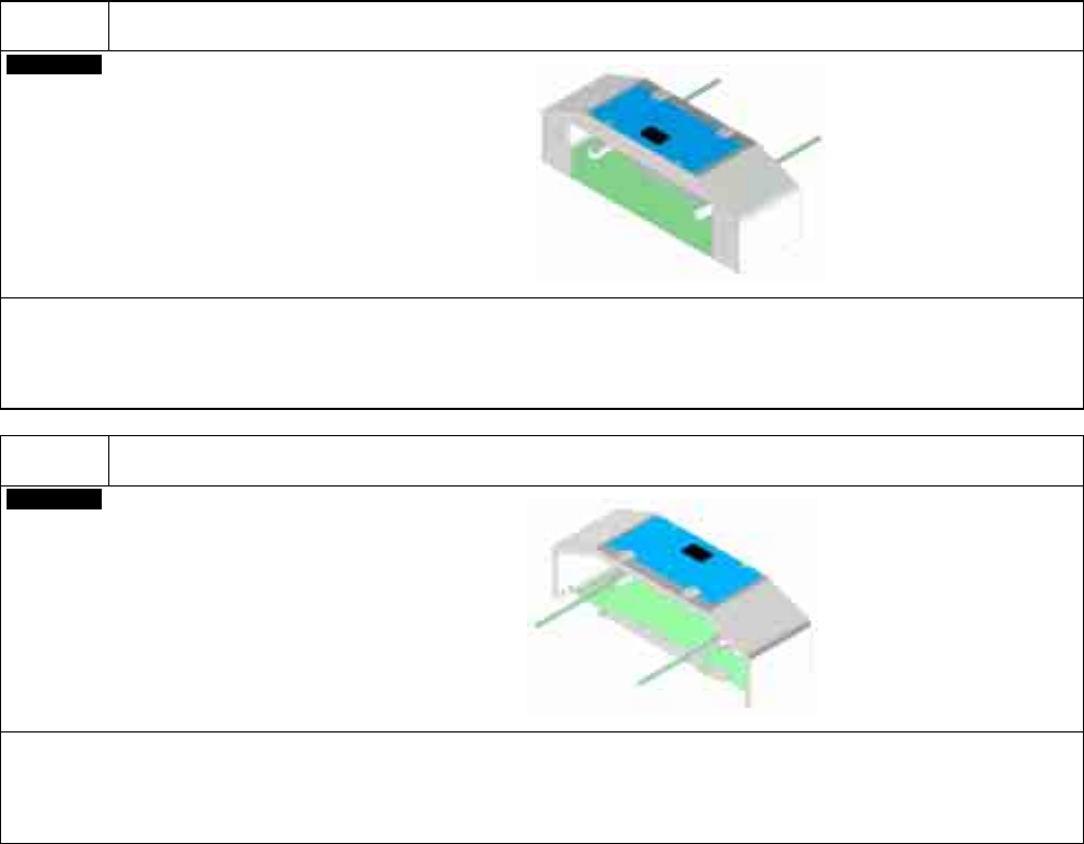
A-5
To get space after the upstream machine.
Factory
Upstream extension conveyor
・
As standard, one PCB of up to 330 mm long can stand by before the placement stage. But the addition of the upstream
extension conveyor will let a PCB of up to 510 mm long stand by.
When this option is selected, please note that the safety sensor will not be installed to the PCB entrance because a safe
distance between the entrance and the moving part is secured.
A-6
To provide the post placement standby area for the transfer downmost stream area.
Factory
Downstream extension conveyor
・
As standard, no PCB can stand by after the placement stage. But the addition of the downstream extension conveyor
will let a PCB of up to 510 mm long stand by.
When this option is selected, please note that the safety sensor will not be installed to the PCB exit because a safe
distance between the exit and the moving part is secured.
L = 305 mm
L = 305 mm