CM602规格说明书(英文).pdf - 第50页
CM602-L 2006.0515 - 45 - B-1 To change th e pos itions of PCB supp ort p ins extern ally, in ord er to re duce the c hange over tim e. Customer PCB supp ort block ・ The machine come s with four PCB supp ort blocks to be …
CM602-L 2006.0515
- 44 -
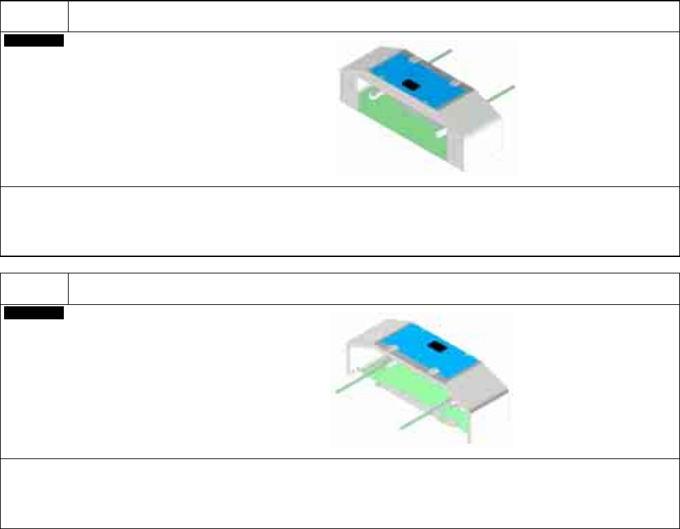
A-5
To get space after the upstream machine.
Factory
Upstream extension conveyor
・
As standard, one PCB of up to 330 mm long can stand by before the placement stage. But the addition of the upstream
extension conveyor will let a PCB of up to 510 mm long stand by.
When this option is selected, please note that the safety sensor will not be installed to the PCB entrance because a safe
distance between the entrance and the moving part is secured.
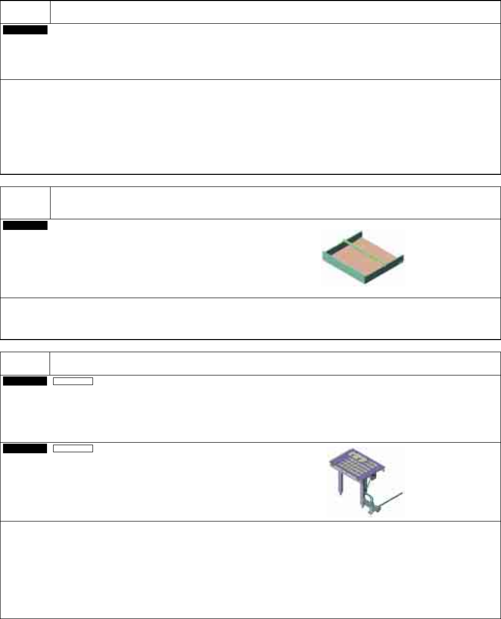
A-6
To provide the post placement standby area for the transfer downmost stream area.
Factory
Downstream extension conveyor
・
As standard, no PCB can stand by after the placement stage. But the addition of the downstream extension conveyor
will let a PCB of up to 510 mm long stand by.
When this option is selected, please note that the safety sensor will not be installed to the PCB exit because a safe
distance between the exit and the moving part is secured.
L = 305 mm
L = 305 mm
CM602-L 2006.0515
- 45 -
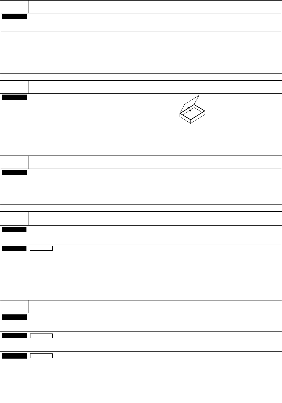
B-1
To change the positions of PCB support pins externally, in order to reduce the changeover time.
Customer
PCB support block
・
The machine comes with four PCB support blocks to be set and used for placement.
(Because the number of support pins is 20 per block, a total of 80 pins is included as standard.
Additional purchase by the block (20 pins) is available.)
・
If requiring more PCB support blocks for external preparation, please purchase as many ones as you need.
・
To set up the positions of support pins for new PCB externally, please purchase “Support pin setting jig”
[option] separately.
・
Common to CM402-L, CM401-L, and DT401-F.
Not sharable with CM402-M, CM401-M, CM400-M, DT401-M, DT400-M, CM212-M, CM202/201, and CM301.
B-2
To set up the positions of support pins for new PCB externally, in order to reduce the changeover
time.
Customer
Support pin setting jig
・
To prepare the support pins externally, please purchase the “PCB support block” [option] separately.
・
Common to CM402-L, CM401-L, and DT401-F.
Not sharable with CM402-M, CM401-M, CM400-M, DT401-M, DT400-M, CM212-M, CM202/201, and CM301.
B-3
To automate the nozzle changing operation in changeover.
On-site
By stage
Nozzle changer (for High Speed head (12 nozzles))
(This holds 36 nozzles.)
On-site
By stage
Nozzle changer (for High Speed head (8 nozzles))
(This holds 28 small nozzles and 2 large nozzles.)
・
In the High Speed head specifications, the nozzle changing for the optimum nozzle layout is supported in changeover.
・
In the High Speed head specifications, automatic nozzle changing operation is carried out exclusively in changeover.
Reason)
①
If nozzles are changed during the placement of one PCB, the placement tact time will be affected.
②
Since there are 24 and 16 attachable nozzles per stage for High Speed head (12 nozzles) and High Speed
head (8 nozzles) respectively, the nozzles for High Speed head cannot be changed during operation.
・
Using the nozzle changer may shorten the life of nozzles and nozzle holders.
(In the High Speed head specifications, their life is about three years if changed 10 times a day.)
・
The multi-functional head comes standard with the nozzle changer. (Please see D-5.)
CM602-L 2006.0515
- 46 -
C-1
To select the nozzle to the production pattern.
Customer
Nozzle
・
All nozzles are options so that you can select the best combination of them to make full use of CM602-L to your pro-
duction pattern.
・
For information about the nozzle types, please see “4-2 Nozzle Type & Configuration”.
・
For information about the special nozzles, please contact us.
・
The nozzles are compatible with CM402, CM401, CM400, DT401, DT400, and CM212.
・
For information about the compatibility with CM202/201 and CM301, please contact us.
C-2
To store nozzles.
Customer
Nozzle case
・
The one for the High Speed head can accommodate 50 small nozzles and 10 large nozzles (Another box).
・
The one for the Multi-functional head can accommodate 24 nozzles.
・
The nozzle case is compatible with CM402, CM401, CM400, DT401, DT400, and CM212.
C-3
To select the tape feeder to the production pattern.
Customer
Tape feeder
・
Please refer to “4.4 Feeder Carriage Configuration” for tape feeder types.
・
The tape feeder is compatible with CM402, CM401, CM400, DT401, and CM212.
C-4
To use the 32 mm adhesive tape.
Customer
32 mm adhesive tape feeder
Factory
By table
Air supply unit for the feeder
・
Please refer to “4.4 Feeder Carriage Configuration” for tape feeder.
・
The tape feeder is compatible with CM402, CM401, CM400, DT401, and CM212.
・
To use the adhesive tape feeders, the machine needs the required number of air supply unit for the feeder (1 set per
table). (Please see C-7.)
C-5
To use the tape feeder of 21 mm deep.
Customer
Tape feeder (boss of 21 mm deep maximum)
On-site
By table
Cutting unit for 21 mm thickness T/F (adapter)
On-site
By table
Feeder cart for 21 mm thickness T/F (adapter)
・
Please refer to “4.4 Feeder Carriage Configuration” for tape feeder.
・
The tape feeder is compatible with CM402, CM401, CM400, DT401, and CM212.
・
To use the tape feeders with the boss of 21 mm deep, choose both the Cutting unit for 21 mm thickness T/F and the
Feeder cart for 21 mm thickness T/F.
∗
When this option is installed, tape cutting sound may become louder.