CM602规格说明书(英文).pdf - 第55页
CM602-L 2006.0515 - 50 - C-11 To im prove the work abilit y of tape sp licing. Customer Spli cing cart ・ This cart improves the worka bility of t ape splic ing. ・ The splicin g cart i s compatible with CM 402, CM 401, CM…
CM602-L 2006.0515
- 49 -
C-10
To place tray feeding components.
On-site
Shuttle tray feeder ST40S-20
(2 tray magazines and 20 tray pallets included)
・
The shuttle tray feeder ST40S-20 can be one or tow installed on the rear side of CM602-L main body.
It cannot be installed on the front side.
・
The power will be supplied from CM602-L.
The rated capacity of CM602-L allows the shuttle tray feeders to be connected.
・
To install the shuttle tray feeder, “Extension conveyor for shuttle tray feeder” (recommended) needs to be selected.
Factory
Shuttle tray feeder installation ready
・
To support the shuttle tray feeder, the following cables need to be incorporated inside CM602-L in order for the con-
trolled coupling between CM602-L and the shuttle tray feeder:
c Power cable: one type (for side A / for side B)
d Signal cable: two types (for side A / for side B)
On-site
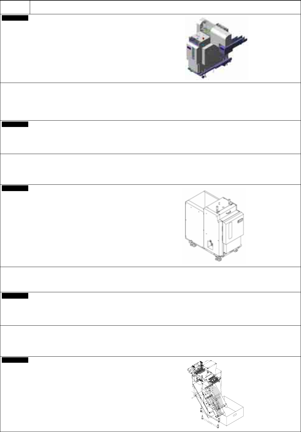
Direct tray feeder DT50S-20
(2 tray magazines and 21 tray pallets included)
・
DT50S-20 holds a maximum of 20 types of trays.
・
One / One or two tray feeders can be connected for type D-0, D-1, E-0 / F-0 respectively.
・
“Direct tray feeder installation ready” and “6-row feeder base mount” need to be selected.
Factory
Direct tray feeder installation ready
・
To support the direct tray feeder, the following cables need to be incorporated inside CM602-L in order for the controlled
coupling between CM602-L and the direct tray feeder:
c Power cable: one type (for side A / for side B)
d Signal cable: two types (for side A / for side B)
Factory
6-row feeder base mount
CM602-L 2006.0515
- 50 -
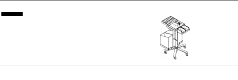
C-11
To improve the workability of tape splicing.
Customer
Splicing cart
・
This cart improves the workability of tape splicing.
・
The splicing cart is compatible with CM402, CM401, CM400, DT401, CM212, CM202/201, and CM301.
CM602-L 2006.0515
- 51 -
C-12
To maintenance the Intelligent feeder.
Customer
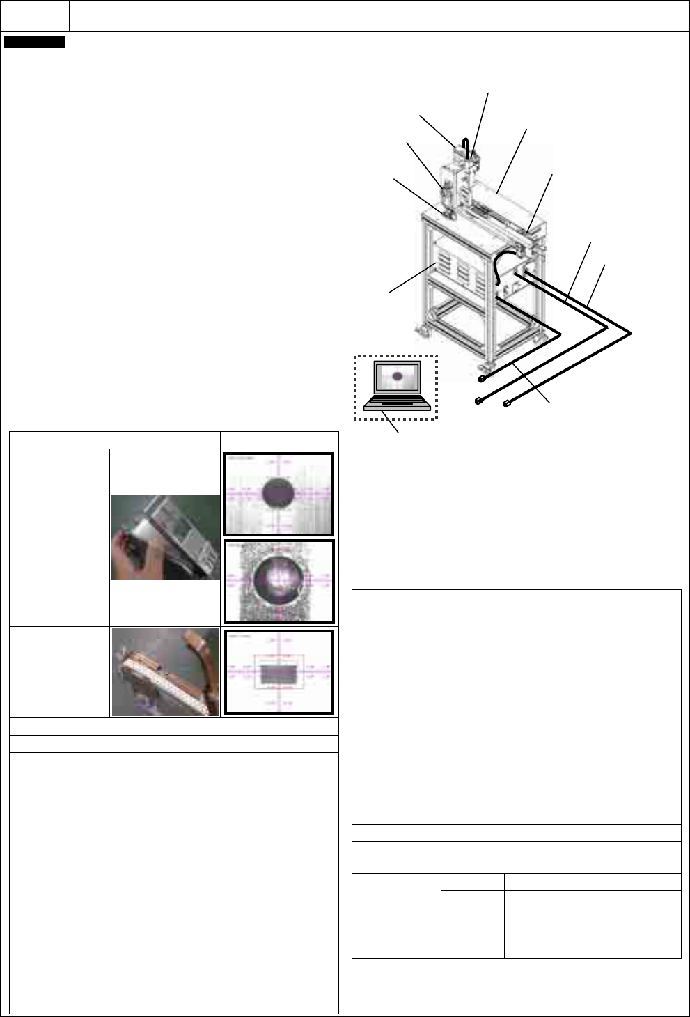
Intelligent Feeder Check Unit (Model No.: NM-EJW2A)
1. General Description
The intelligent feeder check unit allows the customer to per-
form maintenance on the intelligent feeders (tape feeders 8
mm to 32 mm wide).
・
A periodic check can be made after a fixed number of
operations.
・
The customer can adjust the component-feeding posi-
tion after replacing the parts of a malfunctioning feeder.
(Limited to components)
・
The feeder maintenance history will be managed on a PC.
∗
To use these functions, the version of the software incorpo-
rated in the feeder needs to be updated to Ver. 4.00 or later.
(This unit can update the software to Ver. 4.00.)
2. Features
The camera-captured image will be displayed on the PC
screen, not on the dedicated screen any longer; therefore,
the reference position of feed direction can be visually ad-
justed through the use of PC.
Also the target reference frame to be used for adjustment
can be selected from a pull-down list on the PC screen.
Moreover, the dedicated cart with casters provides easy carrying.
3. Specifications
• Feeder reference position check
PC screen
Check with the jig
tape
Upper:
Pickup position
Lower:
Sprocket position
∗
The pickup and
sprocket positions
can be inspected and
adjusted through the
comparison with the
master jig.
Component
pickup position
check with the
component paper
tape
• Feeder software update function (to Ver. 4.00)
• Feeder maintenance counter reset function (to zero)
• Feeder maintenance history management function
(1)
Details display
The details of work can be displayed by tracing the histo-
ries such as the feeder manufacturer’s serial number and
the version.
(2)
CSV file output
All the information displayed on the history list can be
output to a CSV file.
(3)
Sort function
The histories can be sorted in ascending/descending order
of the item selected on the title bar.
(4)
Search function
A search by date and a search refinement for each item
are available.
(5)
History file compression function
The inspection/adjustment file can be compressed in LZH
format.
(6)
Expire function
All the files within the period of time specified on the screen
can be deleted by pressing the execute button.
Selection of installation location
1. The machine should be placed in a horizontal place.
2. Conditions (No condensation)
• Temperature: 10
°
C to 35
°
C
• Humidity: No condensation
3. Floor space
Enough space (0.5 m wide, 1.5 m deep, and 1.5 m
high or more) should be secured for maintenance.
Item
Description
Target feeder
Intelligent tape feeder
8 mm double tape feeder
(With or without the joint detection sensor)
8 mm single tape feeder
(With or without the joint detection sensor)
12 mm/16 mm tape feeder
(With or without the joint detection sensor)
24 mm/32 mm tape feeder
(With or without the joint detection sensor)
∗
Limited to the standard type.
∗
The 44 mm/56 mm to 104 mm wide tape feeder,
the 32 mm paper adhesive feeder, the bulk
feeder, and the stick feeder are not available for
inspection.
Only the feeding action by switch operation on the
feeder is available.
Dimensions
400 mm wide, 745 mm deep, and 1 155 mm high
Mass
60 k
g
(Master jig and master jig case included)
Service power
source
Single phase AC 100 V to AC 240 V
±
5%
50/60 Hz 60 VA
Pressure
0.29 MPa to 0.34 MPa
Air
∗
Required for the
operation check of
the 32 mm paper
adhesive feeder
and the bulk
feeder
Flow rate
8 L/min (A.N.R.)
Connectable with
φ
4 tube
Picture signal cable
Power cable ∗
1
(AC 100 V to AC 240 V)
∗
2. A PC should be prepared by the customer.
Master jig
Regulator
Valve
Control box
Camera
X-Y table
Jig cart
Communication cable