CM602规格说明书(英文).pdf - 第59页
CM602-L 2006.0515 - 54 - D-4 T o r eplace with H igh S peed head (8 n ozzles ) or High S peed head (1 2 noz zles). On-site By stage High Sp eed head ( 12 n ozzles ) ・ Please sele ct this opt ion if re placing th e High S…
CM602-L 2006.0515
- 53 -
D-1
To place BGA, CSP.
On-site
By table
Side lighting
・
The lighting intended for the bump recognition is necessary for placement BGA and CSP.
・
The stage where the multi-functional head is selected at the time of purchase of the machine comes standard with the
side lighting. The stage where the high-speed head is selected at the time of purchase of the machine comes optional
with the side lighting. Whether the high-speed head or the multi-functional head, a spare head does not come with the
side lighting; therefore, please select this option when needed.
D-2
To detect the floating leads of SOP, QFP, etc.
On-site
By table
Lead checker
・
Floating leads are detected by laser scanning all the leads of SOP, QFP, etc. whose size is 50 mm × 50 mm or under.
・
Please select this for each table on the stage for which the Multi-functional heads are selected.
(It cannot be installed on the High Speed head stage.)
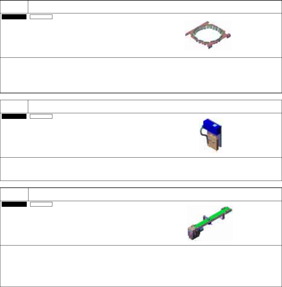
D-3
To align and eject the NG components onto the conveyor.
Customer
By table
NG-components ejection conveyor
・
This is used for ejecting recognition NG components.
・
Please select this for each table on the stage for which the Multi-functional head is selected.
(It cannot be installed on the High Speed head stage.)
・
This option will occupy two feeder setting slots.
・
The NG-components ejection conveyor is compatible with CM402, CM401, CM400, and DT401.
Not sharable with CM212.
CM602-L 2006.0515
- 54 -
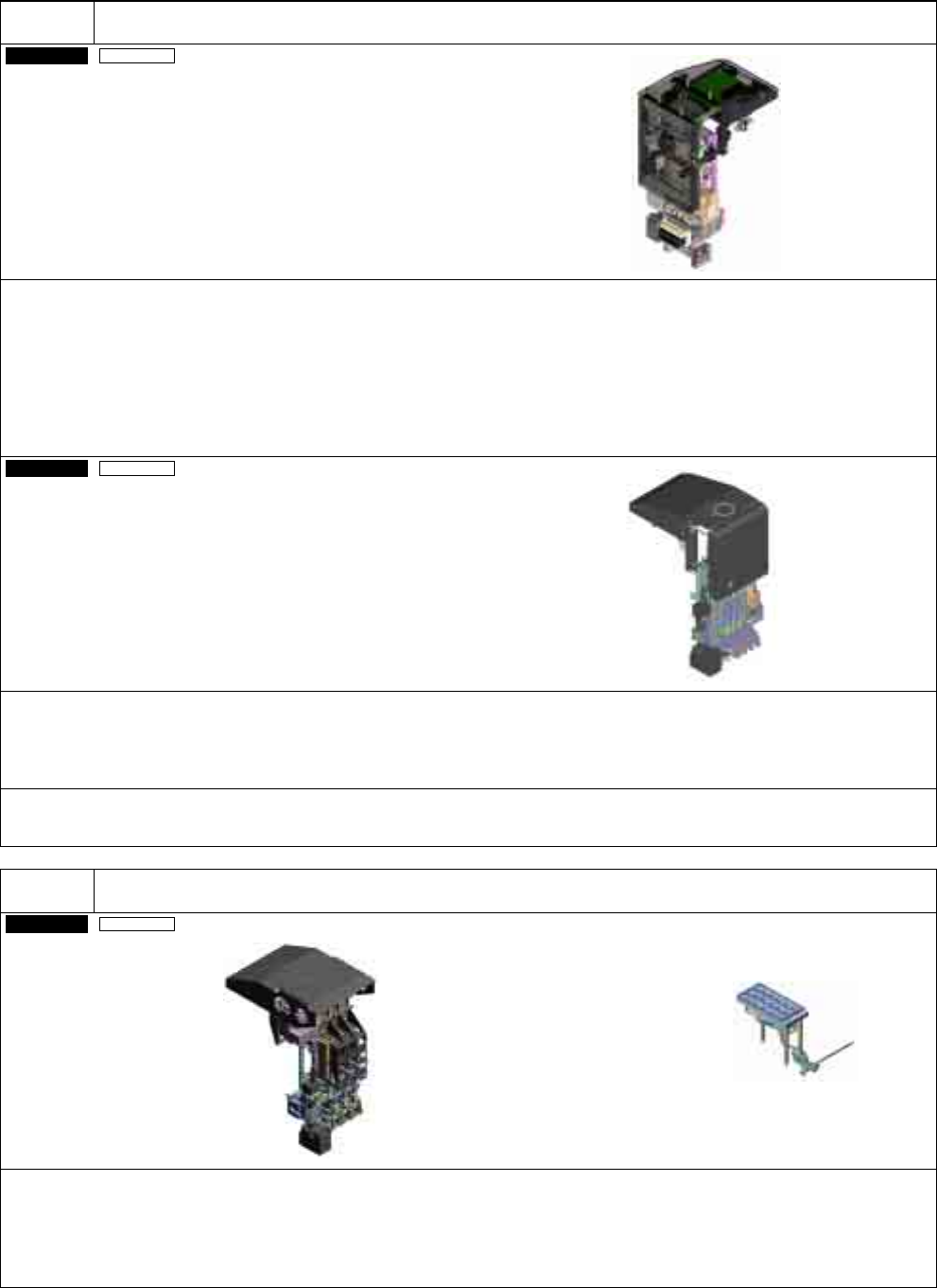
D-4
To replace with High Speed head (8 nozzles) or High Speed head (12 nozzles).
On-site
By stage
High Speed head (12 nozzles)
・
Please select this option if replacing the High Speed head (8 nozzles) or the Multi-functional head with the High Speed
head (12 nozzles).
・
This can be replaced for each stage (two heads). It is not possible to set the different heads onto the front and the rear
table.
・
For High Speed head (12 nozzles) type, the versions of the software incorporated in the double tape feeder and the
feeder cart need to be updated to Ver. 5.00 or later and Ver. 1.20 or later, respectively.
(Because of the gang feed support in right and left lanes of double tape feeder.)
・
Attachments: “Gang feed support” labels (the identification labels for the software-updated feeder and feeder cart)
On-site
By stage
High Speed head (8 nozzles)
・
Please select this option if replacing the High Speed head (12 nozzles) or the Multi-functional head with the High Speed
head (8 nozzles).
・
This can be replaced for each stage (two heads). It is not possible to set the different heads onto the front and the rear
table.
・
For the high-speed head type, the nozzle changer is optional. B-3 “Nozzle changer (for High Speed head)” is required
separately.
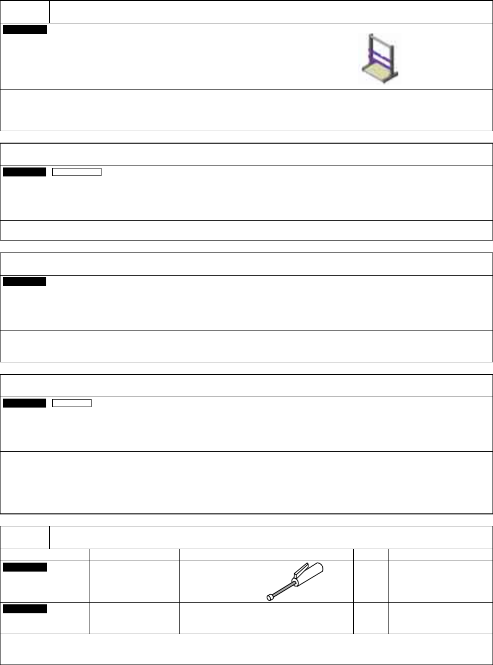
D-5
To replace with Multi-functional head.
On-site
By stage
Multi-functional head
Nozzle changer
(for Multi-functional head)
(This holds 15 large nozzles.)
・
Please select this option if replacing the high-speed head with the multi-functional head.
When needed, please select the optional side lighting (D-1 Side lighting) because it is not included as standard.
・
This can be replaced for each stage (two heads). It is not possible to set the different heads onto the front and the rear
table.
・
Nozzle changer (for the Multi-functional head) is included with the Multi-functional head.
CM602-L 2006.0515
- 55 -
D-6
To manage and store the removed heads.
Customer
Head stand (For two heads)
Head stand (For four heads)
・
This is used to store the removed heads after exchanged.
・
One stand can store two or four heads. Please select either one corresponding to the number of heads to be stored.
・
The head stand is compatible with CM402, CM401, CM400, DT401, DT400, and CM212.
D-7
To place components onto ceramic PCB.
On-site
Whole machine
Ceramic board support
・
For further information, please contact us.
D-8
To use the parts verify function.
Factory
Pana PRO/CVT supporting unit
・
To use the production-support system Pana PRO/CVT, the Pana PRO/CVT supporting unit needs to be
installed to the machine.
D-9
To detect the components brought back.
On-site
By stage
Component thickness sensor
・
This emits a laser light to the nozzle tip to provide component thickness measurement (chip data entry and placement
height control), component bring-back check, and nozzle tip check.
・
The measurable component thickness is 3 mm maximum.
・
This is an option exclusive to High Speed head (12 nozzles) type.
∗
This option will be released in September 2006.
E-1
Required for the regular maintenance.
Option name Usage Description Qty. Remarks
Customer
Lubrication set
Greasing the
designated points
on the machine
Grease gun
Nozzle
1 set
Common to CM402,
CM401, CM400, DT401,
DT400, CM212,
CM202/201, and CM301.
Customer
Maintenance jig
Regular
maintenance
Grease for heads (Syringe included)
Blower brush for cleaning the camera
1 set
Common to CM402,
CM401, CM400, DT401,
DT400, and CM212.
・
These are used for the periodical application of grease and cleaning in machine maintenance, etc.
・
They are necessary in purchasing the first standard machine.