CM602规格说明书(英文).pdf - 第64页
CM602-L 2006.0515 - 59 - 10. Safety Devices CM602-L h as the fol lowin g saf ety devices for the saf ety use of machine. W hen an emer gency stop s witch is press ed or the c over is opene d whil e the m achine is operat…
CM602-L 2006.0515
- 58 -
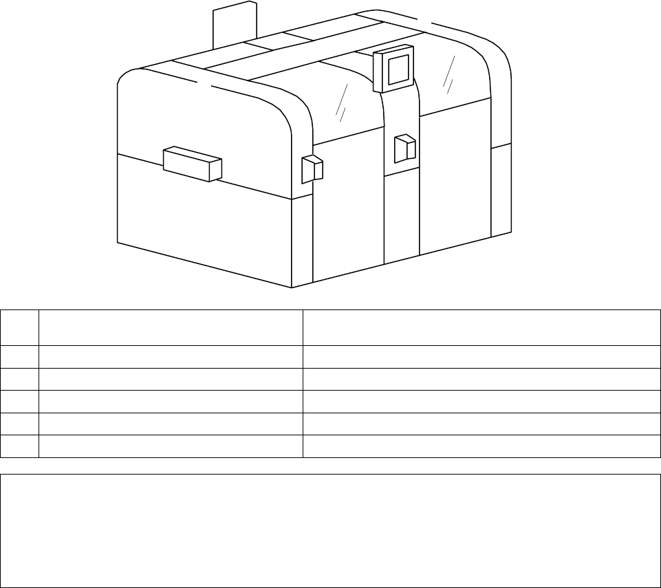
9. Paint Color
■
Standard color
White W-13 (G50)
■
Designation of colors
This page is used when customer needs to designate color.
No.
Place where you can designate the color
(Place painted standard color)
Designated color
(As a rule, color sample is necessary.)
①
Upper cover (Left
・
Right)
②
Upper plate
③
Lower cover (Front
・
Rear)
④
Frame side cover (Left
・
Right)
⑤
Transfer unit cover (Left
・
Right)
* The following cannot change the original color.
・
Open/Close cover frame (black)
・
Feeder cart
・
Main operating area (Front
・
Rear)
・
Y-axis motor cover (4 locations)
・
Touch panel cover (Front
・
Rear)
②
③
③
③
④
⑤
①
①
②
②
CM602-L 2006.0515
- 59 -
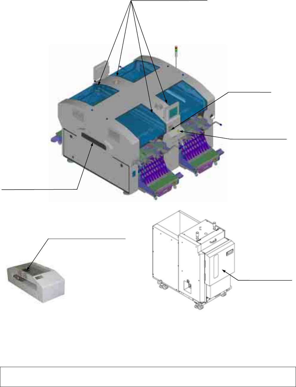
10. Safety Devices
CM602-L has the following safety devices for the safety use of machine.
When an emergency stop switch is pressed or the cover is opened while the machine is operating, the operation
is forcibly stopped.
(
∗
) The safety sensor will not be installed to the transfer opening where the optional extension conveyor is installed. When the optional
extension conveyor is installed, a safe distance between the transfer opening and the moving part is secured. The open/close detection
switch is installed to the cover of the optional extension conveyor.
∗∗
Remarks
∗∗
•
Check enough the separate instruction manuals and the warning instructions of equipment to operate the
machine properly, regardless of operating or stopping it, for the safety use of it.
Cover open/close detection switch
(
×
4 on both sides)
Emergency stop switch
(
×
2 on both sides)
Servo switch
(
×
2 on both sides)
Transport opening safety sensor
(
∗
)
(On the upstream and the
downstream side: Two in total)
Emergency stop switch
(One place)
Direct tray feeder (option)
Extension-conveyor (optional)
cover open/close detection switch
(On the upstream and the
downstream side: One each)
CM602-L 2006.0515
- 60 -
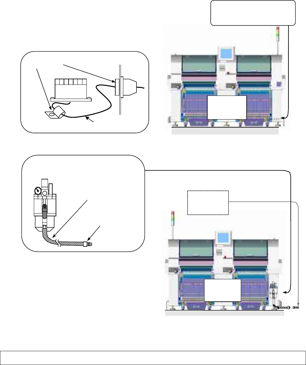
11. Electric / Pneumatic
11.1 Electric Source Unit
■
The power source should be connected with four-conductor cable of AWG#12 or larger.
(This cable is not included.)
■
The cable should be clamped in two points as the lower-left figure shows.
[Recommended]
1. Terminal connecting pin
Manufacturer: Weidmüller
Type: H4/20D or H6/20
2. Outside diameter dimensions of the cable
φ
13.5 mm to
φ
18.0 mm
3. Be sure to secure the cable with the cable clamps
so that it will not be moved by being pulled
(100 N) or turned.
11.2 Pneumatic Source Unit
∗∗
Remarks
∗∗
•
Please prepare the electric source cable of a customer.
■
Pneumatic Source unit
(Located inside the cover)
Coupler (Nittoh)
30PH
Reinforced tube
5 m
Socket (Nittoh)
30SH
CM602-L
Rear side of
the machine
Electric source unit
Terminal block
(Located inside the cover)
Cable clamp
Terminal
block
Cable
CM602-L
Front side of
the machine