CM602规格说明书(英文).pdf - 第67页
CM602-L 2006.0515 - 62 - ■ Adjust Bolt Diagram Model: CM602-L (Unit: mm) Electric sour ce Air 0.49 MPa to 0.7 8 M Pa 980 175 520 175 Conveyor reference plane 1 850 85 85 1 020 1 020 2 210 Worker side
CM602-L 2006.0515
- 61 -
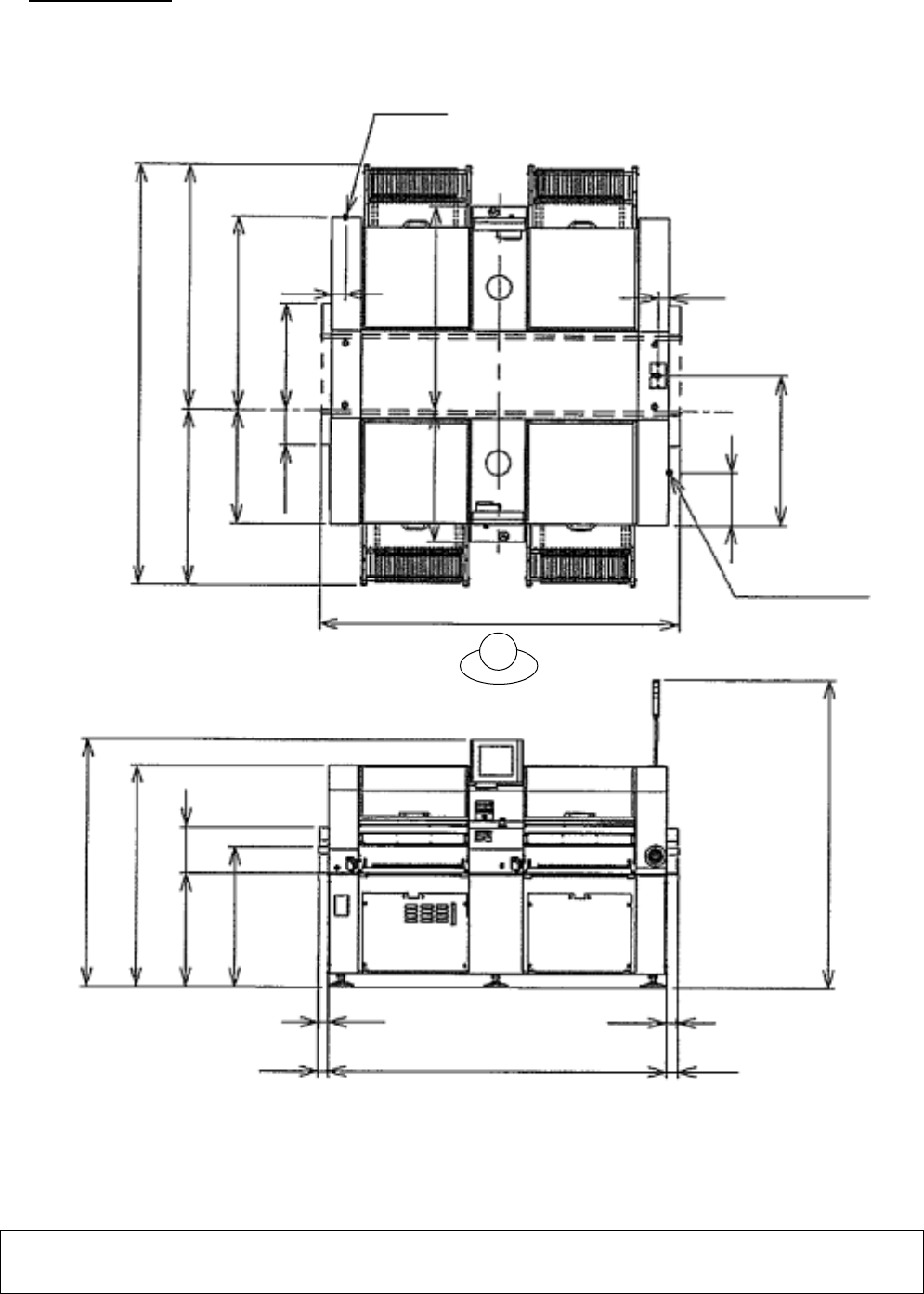
12. Dimensions
Model: CM602-L
(Unit: mm)
∗∗
Remarks
∗∗
•
The above Illustrations do not strictly agree with the actual machine in a reduced scale.
When examining the line configuration, dimensions, etc., please ask for the materials for them.
2 690
1 575 1 115
1 255 735
225 685
850 1 330
340
965
87
73
Electric source
2 350
AIR
1 600
1 430
734 294
900
2 000
2 210
70
65 65
70
Worker side
CM602-L 2006.0515
- 62 -
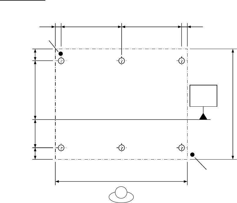
■
Adjust Bolt Diagram
Model: CM602-L
(Unit: mm)
Electric source
Air
0.49 MPa to 0.78 MPa
980 175
520
175
Conveyor
reference
plane
1 850
85 85
1 020 1 020
2 210
Worker side
CM602-L 2006.0515
- 63 -
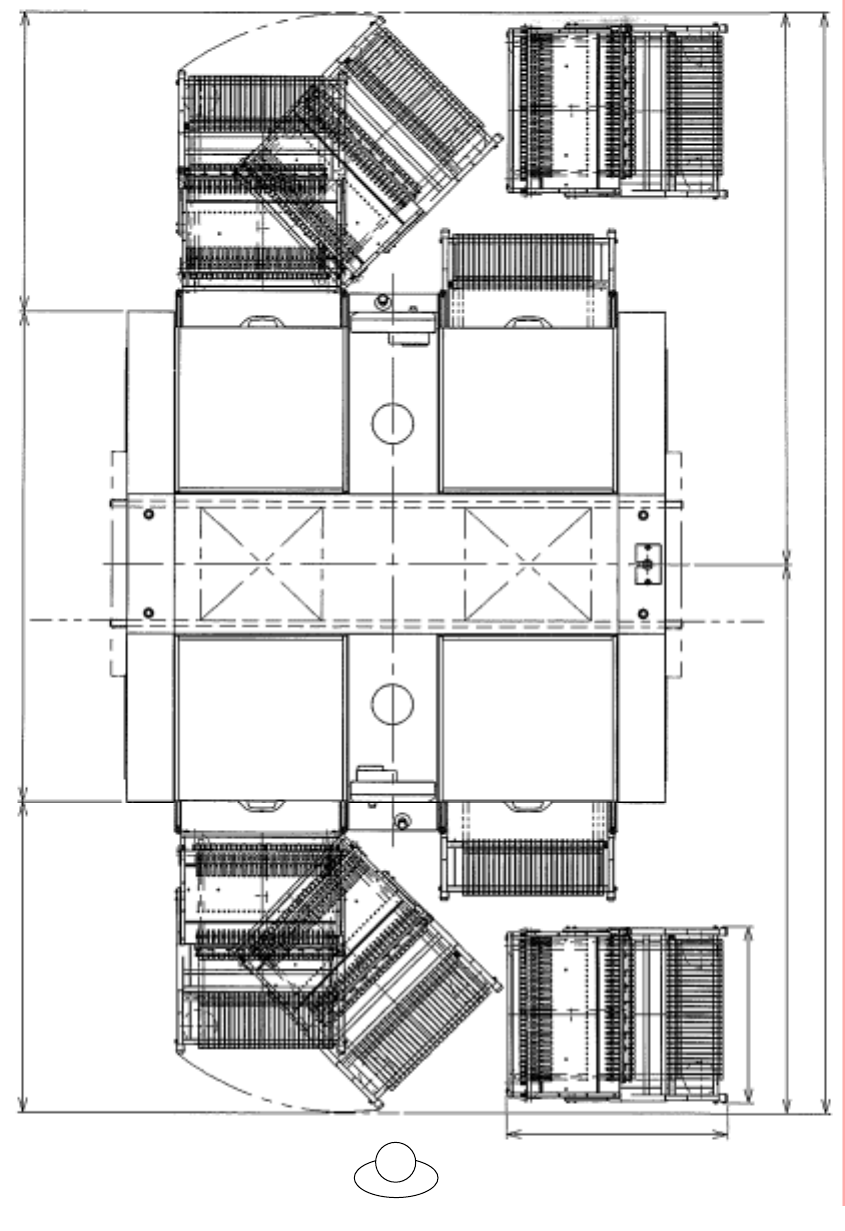
When exchanging the feeder cart, it is a necessary minimum space.
Be careful at the time of machine installation.
(Unit : mm)
* The floor slope in the feeder cart installation area needs to be 6 mm or less in the right/left direction and
11 mm or less in the forward/backward direction. If the floor slope is beyond the above limit, the feeder cart
cannot be taken in and out.
902
1 220
1 990 1 260
715
2 225
4 470
2 245
Worker side
Worker side