CM602规格说明书(英文).pdf - 第7页
CM602-L 2006.0515 - 2 - PCB exc hange tim e For CM602- L, two PCBs ca n be clam ped on one stage . (PCB lengt h: 240 m m or less) W hen two PCBs are c lam ped, after th e placem ent of the PCB on the do wnstream side is …
CM602-L 2006.0515
- 1 -
1. General Description
■
High Productivity
The installation of new-style heads and new-style line cameras, the adoption of linear motors, and the de-
velopment of high-speed multi-head system provide high-speed placement. We have pursued also the high
operating rate through the reduction in the PCB exchange time, the feature of the chip supply during op-
eration, and the optimum arrangement onto each stage.
■
Versatility
It has inherited the modular design concept of CM400 series, ensuring compatibility with the CM400 series.
It is possible to combine the “High Speed head (12 nozzles)” suitable for super-high speed placement of
microchips, the “High Speed head (8 nozzles)” suitable for high speed placement of microchips to
medium-size components, and the “Multi-functional head” that supports various kinds of irregular-shaped
components. We also support changing head after purchase.
■
Efficient Changeover
The multi job production, meaning that only one time preparation enables the production of great many
models, is supported. Additionally, the preparation for the next model while the machine is operating, and
an offline preparation can be performed. An optimum changeover to your production pattern is possible.
■
High Accuracy Placement
Components are placed at high speed and high precision, through the newly developed recognition system,
calibration feature, and high speed low vibration control.
2. Features
High Productivity
Placement tact time
The installation of new-style lightweight heads and new-style high-speed-recognition cameras, and the adoption
of linear motors provide high productivity.
Each placement stage has two of heads, recognition systems, and feeder tables.
Pick up, recognition, and placement carried out alternately by the two heads with the multi row nozzle
(12 nozzles, 8 nozzles or 3 nozzles) provide a high speed and high accuracy placement.
The multi head system (two heads) is incorporated into two stages; placement is carried out on each stage at the
same time.
∗∗
Remarks
∗∗
•
Optimum conditions mean the placement conditions defined by our original standards.
•
The “High Speed head (8 nozzles)” is identical with the “High Speed head” of CM400 series.
: Head
: Line camera
While one head recognizes and then places components,
another one picks up and then recognizes components.
* High Speed head (12 nozzles) specifications, under optimum conditions
Conceptual illustration of placement.
(High Speed head)
Pick up
Place
Recognition
Recognition
Pick up
Place
0.038 s/chip
(*)
Pick up
Place
Pick up
Place
CM602-L 2006.0515
- 2 -
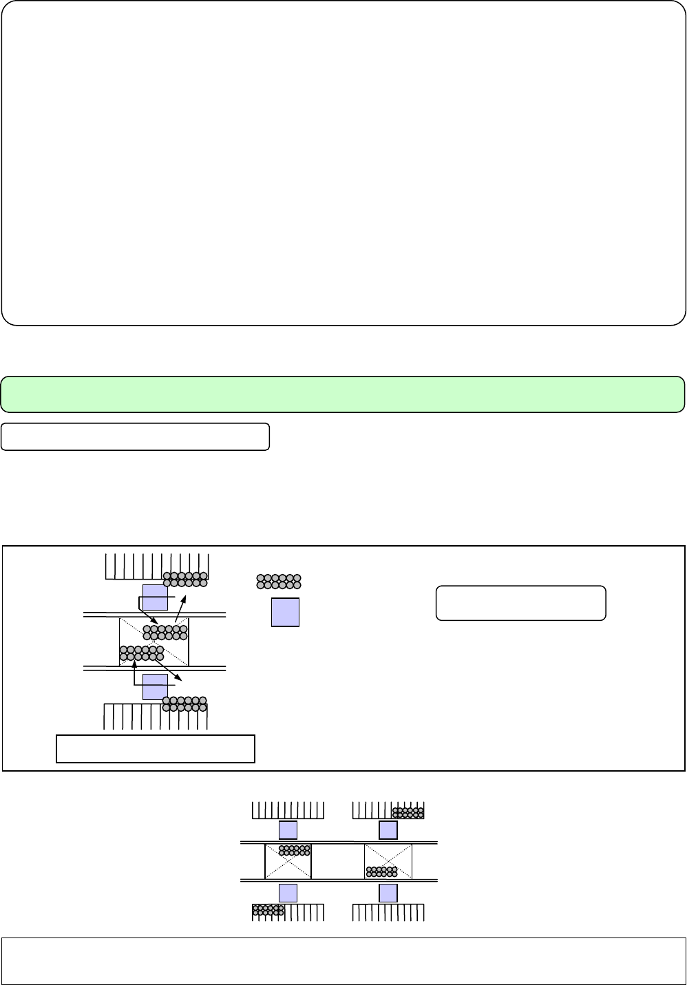
PCB exchange time
For CM602-L, two PCBs can be clamped on one stage. (PCB length: 240 mm or less)
When two PCBs are clamped, after the placement of the PCB on the downstream side is complete, that on the
upstream side is carried out continuously.
For small sized PCBs (L 240 mm × W 240 mm or less), one PCB is replaced by another within
at least 0.9
seconds
(*).
(That is attainable if no components are placed on the back side, and the side clamp and support pins are not
used. The others are based on our measurement conditions.)
* The transfer time varies depending on such conditions as a PCB size and whether the support pins are used or not.
For further information, please contact us.
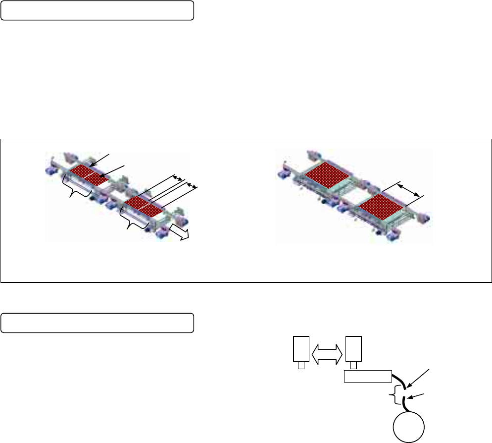
Feature of chip supply during operation
CM602-L has adopted the tape splicing feature, which
allows supplying components while the placement
machine is operating without stopping the placement
operations.
If you register the number of components into the
placement machine data beforehand, you will have the
notice of component empty.
Tape feeder
Ne
Splicing
Trailing edge of tape
During operation
Tip of tape
Next
reel
For the large PCB as that for
personal computer
For small and middle sized PCBs as those for mobile telephone,
personal handyphone system, and digital camera
240 mm or less
240 mm or less
First placement position
Second placement position
Placement stage A
Placement stage B
Transport direction
240 mm
to 510 mm
CM602-L 2006.0515
- 3 -
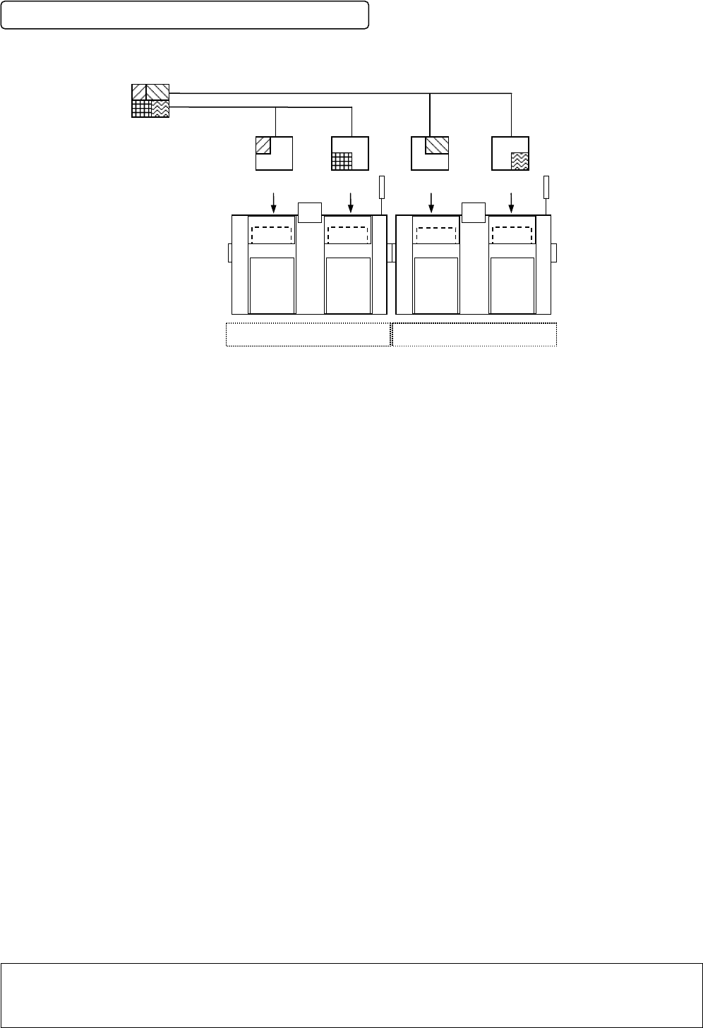
Support for machine coupling (modularizing)
CM602-L supports for coupling (modularizing);
multiple machines (up to eight stages) can be coupled
.
∗∗
Remarks
∗∗
•
Example of coupling: When all the machines are CM602-L, up to four of them can be coupled.
•
If the number of the machines to be coupled exceeds four as a result of the combination of CM602-L, the
switching hub needs to be installed on the fifth machine or later.
< Conceptual illustration of the data distribution in the case of two
machines (four stages), CM602-L + CM602-L >
Stage
Placement data
A
uto distribution
A
uto distribution
A
uto distribution
Placement
data
CM602-L CM602-L
Placement
data
Placement
data
Placement
data
A
uto distribution
Stage
StageStage