00196430-0102-AI_Head_Reconfiguration_Kit_SX_CPP_en_de - 第65页
Installing the CPP Placement Head Connecting Data and Pneumatic Lines Assembly of the CPP Placemen t Head Assembly Instructions / Montageanleitung Head Reconfiguration K it CPP 65 Connectin g Data and Pneumati c Lines 3.…
Installing the CPP Placement Head
Assembly of the CPP Placement Head Fitting the Component Camera
64 Assembly Instructions / Montageanleitung Head Reconfiguration Kit CPP
Installation
See also
2.3 Requirements and Restrictions for the CPP Placement Head [ ➙ 50]
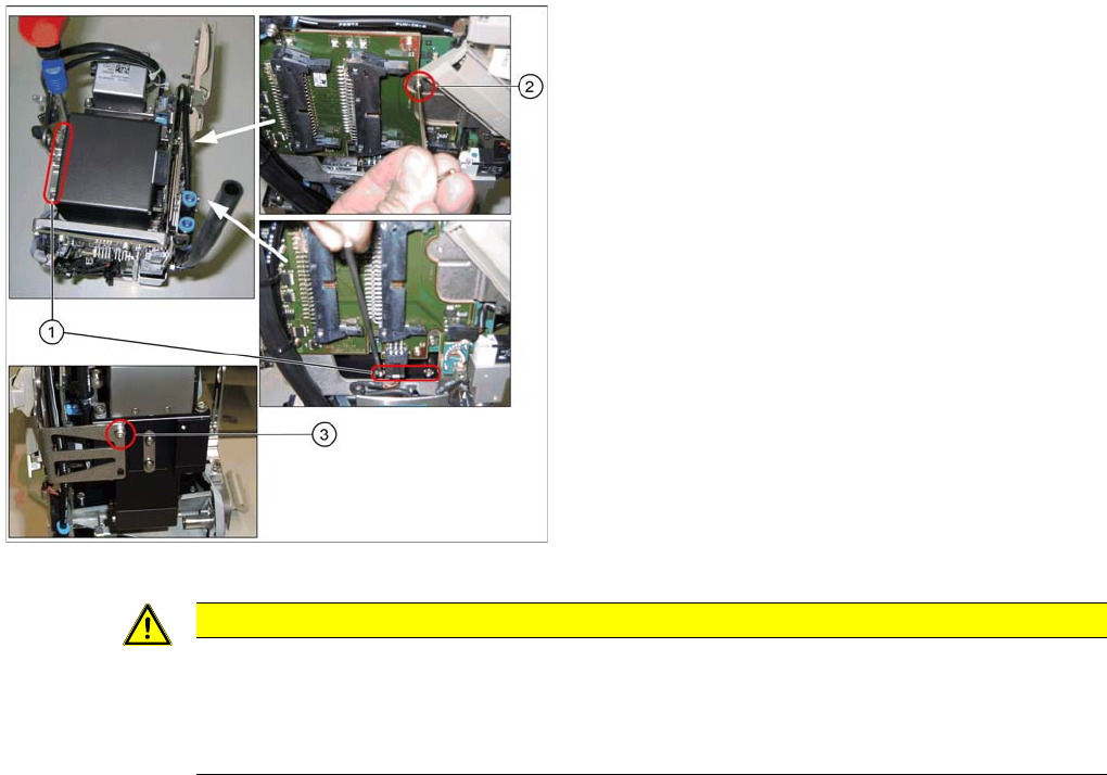
Installing the component camera
Legend
1. 4 screws at the foot of the camera DIN 912-M3 x 16-
A2-70 [00325349-xx]
2. Screw on the board holder ISO 4762 - M 2,5 x 4-A2-
70 [03042531-xx ] DIN 125-A 2.7-140HV-A2
[00201583-xx]
3. Screw on the retaining bracket ISO 4762 - M 2,5 x 4-
A2-70 [03042531-xx ] DIN 125-A 2.7-140HV-A2
[00201583-xx]
► Carefully place the component camera onto the locat
-
ing pins at the CPP head.
► Fasten the component camera to the CPP head with
four screws (1) and with one screw to the board hold
-
er (2).
► Fasten the component camera to the retaining brack
-
et (3).
CAUTION
Installation instructions
► Make sure that you do not damage or contaminate the camera optical system.
► Use a torque screwdriver for the component camera fixing screws. Tighten the 4 lower fix
-
ing screws with a torque of 145 Ncm.
Installing the CPP Placement Head
Connecting Data and Pneumatic Lines Assembly of the CPP Placement Head
Assembly Instructions / Montageanleitung Head Reconfiguration Kit CPP 65
Connecting Data and Pneumatic Lines
3.4.3 Connecting Data and Pneumatic Lines
Inserting the CPP Head Into the Machine
3.4.4 Inserting the CPP Head Into the Machine
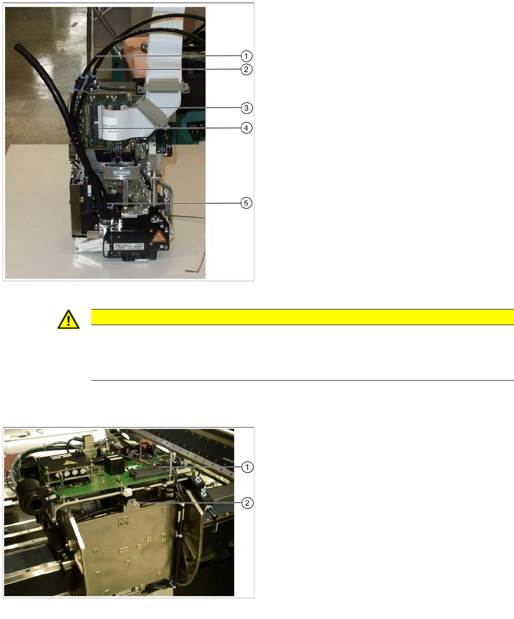
Data and pneumatic lines on the CPP head
Legend
1. Pneumatic hose of the holding circuit [03077181-xx]
2. Pneumatic hose of the pickup / placement circuit
[03077181-xx]
3. Right plug (X2) of the flat ribbon cable to the head
adapter [03055515-xx] (plug X2 behind the flat ribbon
cable)
4. Left plug (X1) of the flat ribbon cable to the head
adapter [03055515-xx] (plug X1 in front of the flat rib
-
bon cable)
5. Discharged air hose to silencer
► Connect the two pneumatic hoses (1) and (2).
► The discharged air hose is already connected to the
head (5).
► Plug the two connectors of the flat ribbon cables to
the left (4) and the right connector (3) of the CPP
head.
CAUTION
The left cable on the head (X1) belongs to the front connector (X1) on the head adapter. The
right cable on the head (X2) belongs to the rear connector on the head adapter (X2). The cables
lie "inside one another". Otherwise the machine will stop with an error during startup. In some
cases it is possible that parts of the machine will be destroyed.
Hanging up the CPP head
Legend
1. Connections for flat ribbon cables of head adapter
2. Hook for hanging up the head
► Hang the head on the hook with its retaining bracket
(2).
► Slightly lift the head (0.5 mm) so that it engages in its
final position and hold it in this position.
Installing the CPP Placement Head
Assembly of the CPP Placement Head Connecting the CPP Head
66 Assembly Instructions / Montageanleitung Head Reconfiguration Kit CPP
Connecting the CPP Head
3.4.5 Connecting the CPP Head
► Connect the discharged air hose (2) to the silencer.
► Close the second connection at the silencer with the cover cap (1).
► Connect the flat ribbon cable to the head adapter (3).
► Connect the two connectors to the component camera (4).
► Tighten the cable holder (strain relief) of the component camera cable (5).
► Connect the pneumatic hoses of the pickup / placement circuit (6) and the holding circuit (7) to the
compressed air distributor.
► Close the remaining connections on the compressed air distributor with the appropriate blanking
plugs: two plugs QSC-4H [00330249-xx] and one plug QSC-12H [03015210-xx].
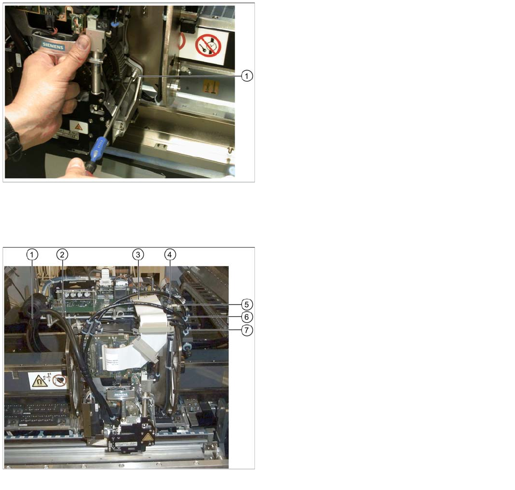
Tighten the CPP head
Legend
1. Head screw on the head
► Tighten the head with the four head screws. Make
sure to use the correct height, the correct screw
lengths and the correct torque: DIN912 M4x18 - 8.8
[00095023-xx], torque: 2.7 N.
Connecting data and pneumatic lines
Legend
1. Cover cap on the silencer [03006728-xx]
2. Discharged air hose to silencer
3. Flat ribbon cable to the head adapter [03055515-xx]
4. Component camera connector
5. Cable holder of the component camera cable
6. Pneumatic hose of the pickup / placement circuit
[03077181-xx]
7. Pneumatic hose of the holding circuit [03077181-xx]