00196430-0102-AI_Head_Reconfiguration_Kit_SX_CPP_en_de - 第67页
Installing the CPP Placement Head Settings On the Base Adapter Assembly of the CPP Placement Head Assembly Instructions / Montageanleitung Head Reconfiguration K it CPP 67 Settings On the Ba se Adapter 3.4.6 Settings On …
Installing the CPP Placement Head
Assembly of the CPP Placement Head Connecting the CPP Head
66 Assembly Instructions / Montageanleitung Head Reconfiguration Kit CPP
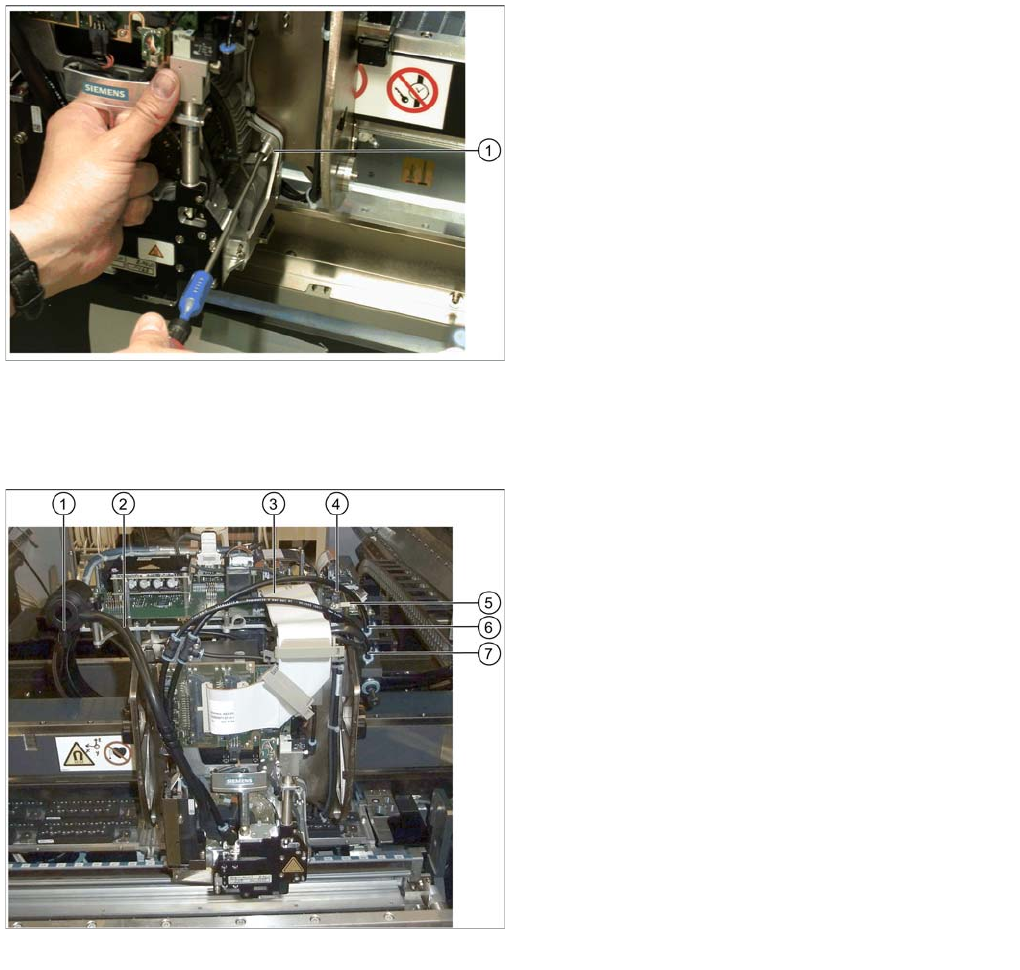
Connecting the CPP Head
3.4.5 Connecting the CPP Head
► Connect the discharged air hose (2) to the silencer.
► Close the second connection at the silencer with the cover cap (1).
► Connect the flat ribbon cable to the head adapter (3).
► Connect the two connectors to the component camera (4).
► Tighten the cable holder (strain relief) of the component camera cable (5).
► Connect the pneumatic hoses of the pickup / placement circuit (6) and the holding circuit (7) to the
compressed air distributor.
► Close the remaining connections on the compressed air distributor with the appropriate blanking
plugs: two plugs QSC-4H [00330249-xx] and one plug QSC-12H [03015210-xx].
Tighten the CPP head
Legend
1. Head screw on the head
► Tighten the head with the four head screws. Make
sure to use the correct height, the correct screw
lengths and the correct torque: DIN912 M4x18 - 8.8
[00095023-xx], torque: 2.7 N.
Connecting data and pneumatic lines
Legend
1. Cover cap on the silencer [03006728-xx]
2. Discharged air hose to silencer
3. Flat ribbon cable to the head adapter [03055515-xx]
4. Component camera connector
5. Cable holder of the component camera cable
6. Pneumatic hose of the pickup / placement circuit
[03077181-xx]
7. Pneumatic hose of the holding circuit [03077181-xx]
Installing the CPP Placement Head
Settings On the Base Adapter Assembly of the CPP Placement Head
Assembly Instructions / Montageanleitung Head Reconfiguration Kit CPP 67
Settings On the Ba se Adapter
3.4.6 Settings On the Base Adapter
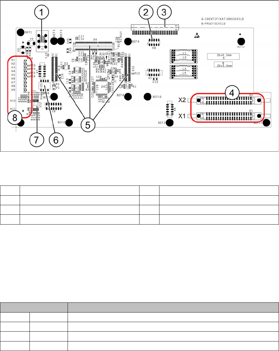
Base adapter for CPP and C&P20A heads (without HCU)
Legend
Switch S1
This switch sets the intermediate circuit voltage for the Z axis.
▪ The switch must be set to 40 V for C&P20 heads.
▪ The setting must be 150 V for CPP heads.
If the setting is incorrect, no damage will be done but an HCU error message will be issued.
DIP switch S2
All switches must be set to OFF. The HCU can be reset with S3, if necessary.
Height Adjustment and Installation of the Nozzle Station
1 Switch S1 (see below) 2 X4 – for checking the voltages
3 Connection to the head interface C700 4 X1 and X2 – to the head
5 X4, X14 and X15 – for the HCU 6 DIP switch S2
7 7 segment display 8 LEDs H1-H11
Switches Description
S1 S0 Gantry encoding (currently not in use)
S2 S1 Gantry encoding (currently not in use)
S3 Reset Reset HCU
S4 Boot Activation of bootstrap function for the HCU (not designed for Service)
Installing the CPP Placement Head
Assembly of the CPP Placement Head Height Adjustment and Installation of the Nozzle Station
68 Assembly Instructions / Montageanleitung Head Reconfiguration Kit CPP
3.4.7 Height Adjustment and Installation of the Nozzle Station
The nozzle station [03073328-xx] is included in the parts set.
When replacing a C&P20A head by a CPP head and vice versa the present nozzle station can be kept.
When replacing a TwinHead by a CPP or a C&P20A head the nozzle station of the parts set must be
installed.
Height Adjustment of the No zzle Station
3.4.7.1 Height Adjustment of the Nozzle Station
CAUTION
► If the COT insert has been removed or shifted during the conversion, the installation height
of the nozzle station should be checked in any case.
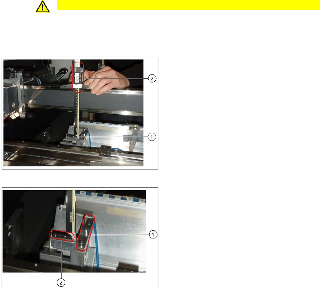
Measuring the height of the nozzle station
► Push the placement head to be measured outwards.
► Place the caliper perpendicularly on the contact sur
-
face of the reject station (1) and measure the dis
-
tance to the guide rail of the gantry.
This distance must be 189mm ± 0.2mm (2).
► If the distance is correct, proceed with the installation
of the nozzle station.
Position for the shim plates
► If the distance is too large, insert shim plates: Shim
plates for nozzle stripping device [03039514
-
xx and
03021079-xx], screws DIN7991 M4x20 - 8.8
[00333782
-
xx].
► If the distance is too small because shim plates have
already been inserted, remove these.