00196430-0102-AI_Head_Reconfiguration_Kit_SX_CPP_en_de - 第70页
Installing the CPP Placement Head Assembly of the CPP Placement Hea d Height Adjustment and Install ation of the Nozzle Station 70 Assembly Instructions / Montageanleitung Head Reconfiguratio n Kit CPP Installi ng the Do…
Installing the CPP Placement Head
Height Adjustment and Installation of the Nozzle Station Assembly of the CPP Placement Head
Assembly Instructions / Montageanleitung Head Reconfiguration Kit CPP 69
Installing the Nozzle Station
3.4.7.2 Installing the Nozzle Station
► Remove the downholder on the right above the reject bin.
► Fit the nozzle station [03073328-xx] with two screws in its mounting position (1).
► Depending on the machine configuration (see "3.4.7.3.1 Configurations with Reject Bins and Coding
Sheet" [ ➙ 70]) insert the reject bin [03048638-xx] and the component reject bin up to 6x6
[03062378--xx]. The reject bin mustn't be higher than the conveyor side wall in any case.
► Fasten the downholder left [03079173-xx] above the reject bin [03048638-xx] (see "3.4.7.3.2 Install
-
ing/Removing Downholder" [ ➙ 73]).
► Insert the coding sheet at unoccupied bin locations [03083883-xx] (see "3.4.7.3.3 Installing/Remov
-
ing Coding Sheet" [ ➙ 74]).
► Install the valve for the nozzle station [03055785-xx] (4) at the COT insert using the two DIN912-
M2,5 x 16-A2-70 screws [00350291-xx].
► Replace, unless already performed, the QSC-6H plug at the solenoid valve feed control with the Y
press-fit connection with push-on socket QSY-6H-4 [03055792-xx].
► Plug the hose PUN-CM 4x0.75 / 200mm [03056096-xx] into the pneumatic connection to the nozzle
changer (5) and into the pneumatic connection of the nozzle changer (6) or close it with the plug
QSC-4H [00330249-xx].
► Plug the hose PUN-CM 4x0.75 / 135mm [03056097-xx] into the pneumatic connection to the nozzle
changer [03055785-xx] (3) and to the pneumatic connection of the nozzle changer (2).
► Connect the cable "Cable feed X series: nozzle station" [03053223-xx] which has already been con
-
nected in the COT insert with the "valve for nozzle station cplt." [03055785-xx].
► If the verify reject bin option is already installed, the sensor for this reject bin has to be installed at
another position. For this, use the metal sensor MK2 prefitted (reject bin 6x6) [03080138-xx]. For fur
-
ther information please refer to the Assembly Instructions Reject Bin SIPLACE SX1/2 [00196615-
xx].
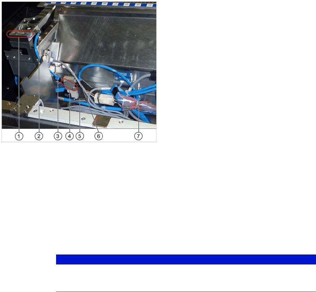
Installing the nozzle station
Legend
1. Fixation points of the nozzle station [03073328-xx]
2. Pneumatic connection on the nozzle station
3. Pneumatic connection to the nozzle station
4. Valve for the nozzle station [03055785-xx]
5. Pneumatic connection to the nozzle changer
6. Fixing screw of the mounting plate
7. Pneumatic connection on the nozzle changer
NOTICE
The mounting plate for the solenoid valve is fastened and fixed in position with one screw only
(6). If necessary, loosen this mounting plate to install the solenoid valve.
Attention: the connector left to the solenoid valve is also fastened to this plate.
Installing the CPP Placement Head
Assembly of the CPP Placement Head Height Adjustment and Installation of the Nozzle Station
70 Assembly Instructions / Montageanleitung Head Reconfiguration Kit CPP
Installing the Downholder and the Co ding Sheet
3.4.7.3 Installing the Downholder and the Coding Sheet
Depending on the configuration of the SX machine either the reject bin [03063238-xx] with downholder
[03079173-xx] or the component reject bin up to 6x6 [03062378--xx] is used on occupied box locations.
On unoccupied bin locations the coding sheet (No Box) [03083883-xx] has to be installed.
For the description of the configurations refer to "3.4.7.3.1 Configurations with Reject Bins and Coding
Sheet" [ ➙ 70].
For the description of the installation and the removal refer to "3.4.7.3.2 Installing/Removing Downhold
-
er" [ ➙ 73] and "3.4.7.3.3 Installing/Removing Coding Sheet" [ ➙ 74].
See also
3.4.7.3.1 Configurations with Reject Bins and Coding Sheet [ ➙ 70]
Configura tions with Reject Bins and Coding S heet
Configurations with Reject Bins and Coding Sheet
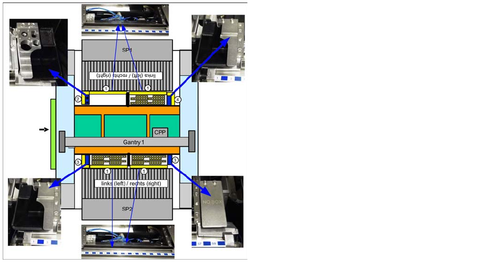
SX 1 without stationary camera
Nozzle station in SP1 right, component reject bin up to
6x6 [03062378--xx] in SP1 and 2, reject bin [03063238-
xx] with downholder [03079173-xx] in SP2 left and SP1
left, coding sheet [03083883-xx] in SP2 right.
Installing the CPP Placement Head
Height Adjustment and Installation of the Nozzle Station Assembly of the CPP Placement Head
Assembly Instructions / Montageanleitung Head Reconfiguration Kit CPP 71
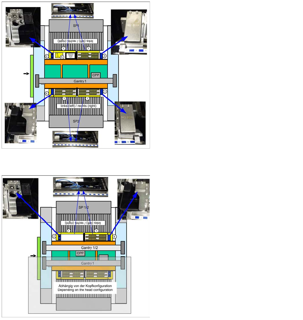
SX 1 with stationary camera
SX2 without stationary camera on one gantry
Nozzle station in SP1 right, component reject bin up to
6x6 [03062378--xx] in SP1 and 2, reject bin [03063238-
xx] with downholder [03079173-xx] in SP2 left, coding
sheet [03083883-xx] in SP1 left and SP2 right
Nozzle station in SP1/2 right, component reject bin up to
6x6 [03062378--xx] in SP1/2, reject bin [03063238-xx]
with downholder [03079173-xx] in SP1/2 left.
On the other gantry: depending on the configuration.