Machine Overview - 第8页
MACHINE OVERVIEW MODULE OVERVIEWS 4.8 Technical Reference Manual Chapter Issue 4 Nov 09 Figure 4-9 High Throughput Conveyor (HTC) Dual Lane The dual lane machine consists of two set s of transport rails, one being a prin…

MACHINE OVERVIEW
MODULE OVERVIEWS
Chapter Issue 4 Nov 09 Technical Reference Manual 4.7
Rising Table
Module
The rising table module fulfils the following functions:
• Provide a stable base and positioning for the board support tooling
• Positioning the transport rails at various heights during the print cycle
Board Support
Tooling Module
The role of the board support tooling is to support the board during the print
stroke, to prevent print distortion caused by flexing of the board as a result of
the downward pressure of the squeegees/ProFlow. Several different types of
board support tooling are available to suit a variety of surface mount process
requirements.
Transport Rails
Module
The transport rail system is a programmable width conveyor system, utilized to
transport the board through the machine and security of the board during the
print stroke. The rail system height is positioned by the rising table, during the
print cycle.
Figure 4-8 Rising Table - Board Support Tooling - Transport Rails
High Throughput
Conveyor
Module
The high throughput conveyor (HTC) module is an optional programmable width
conveyor system. The function of the HTC is to transport up to three boards
through the machine at one time using belts. The rail system height is
positioned by the rising table, during the print cycle.
Transport Rails
Rising Table
Board Support Tooling
MACHINE OVERVIEW
MODULE OVERVIEWS
4.8 Technical Reference Manual Chapter Issue 4 Nov 09
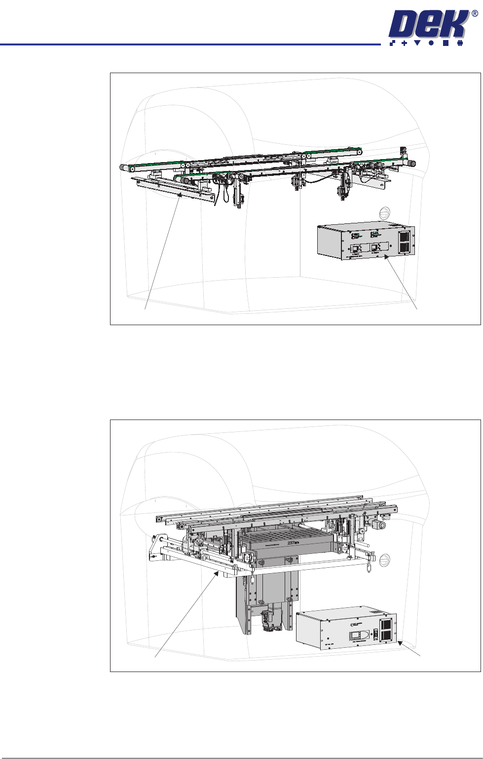
Figure 4-9 High Throughput Conveyor (HTC)
Dual Lane The dual lane machine consists of two sets of transport rails, one being a print
lane and the other being a pass through lane. The machines are a dedicated
build and available as a front print or rear print machine. Dual lane is not an
option that can be fitted to a standard machine.
Figure 4-10 Dual Lane
HTC Module
M27 HTC Controller Enclosure
Dual Lane Module
M40 Dual Lane Controller
MACHINE OVERVIEW
MODULE OVERVIEWS
Chapter Issue 4 Nov 09 Technical Reference Manual 4.9
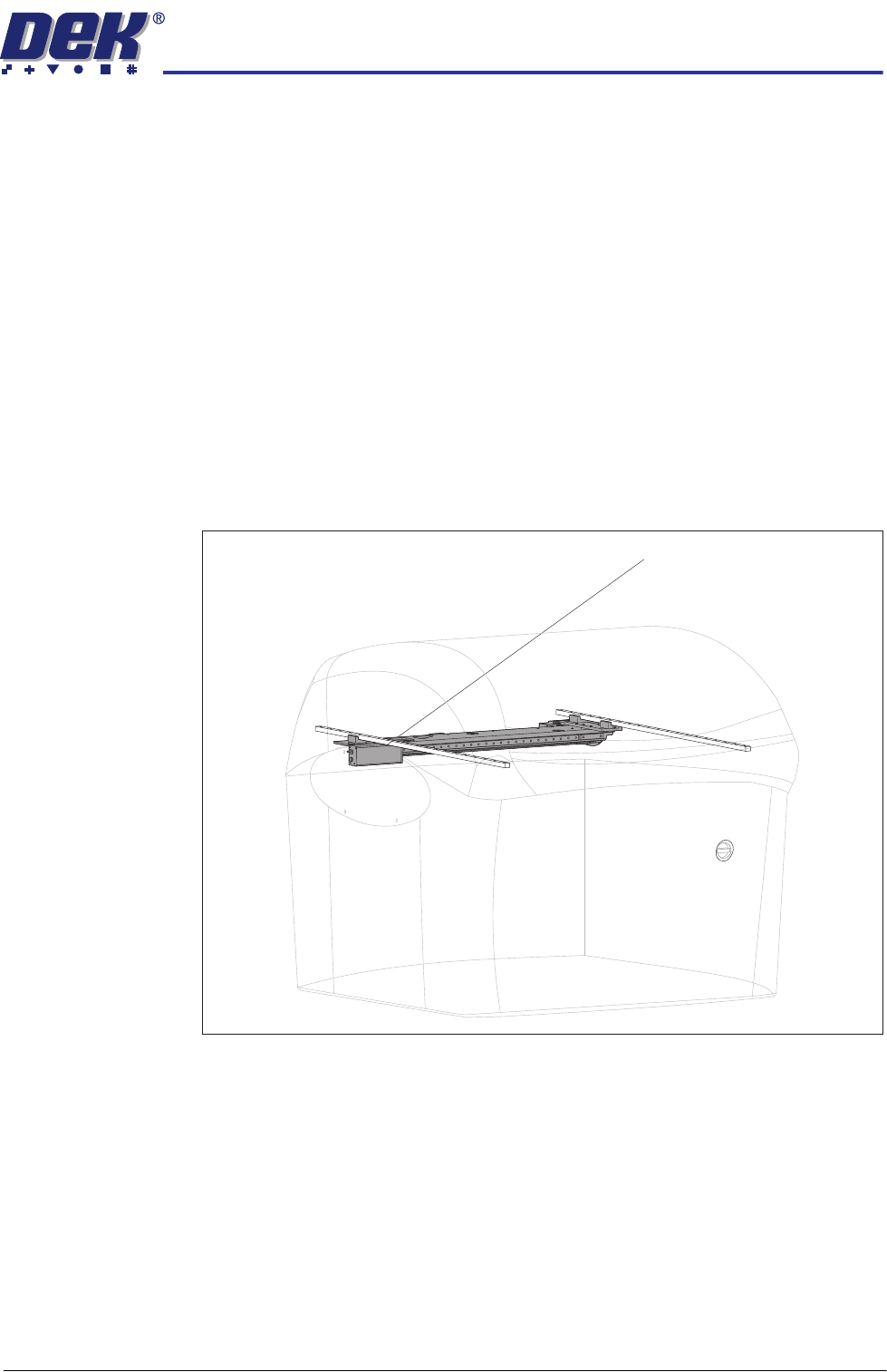
Camera System
Module
The function of the camera system is to supply a visual indication of screen to
board alignment and board/screen inspection data to the machine PC enclo-
sure. The captured information supplied to the PC enclosure enables the
processor to:
• Align the screen to the product board
• Provide visual information for the user on the MMI monitor
The camera assembly traverses horizontally in the X and Y axis and is driven
by either:
• Rotary Servo Motors
• Linear Servo Motors
The camera carriage is also used to transport the board stop and the under-
screen cleaner.
Figure 4-11 Camera System
Camera System