Formflex Manual.pdf - 第19页
1.12 FormFlex Tooling M anual Chapter Issue 4 Jun 04 TECHNIC AL RE FERENCE FAULT FINDIN G F AUL T FINDING Fault Anal ysis W ARNIN G BOARD CLAMPS. EXTREM E CARE MUST BE EXERCISED WHEN WORKI NG IN THE TOOLING AREA OF THE M…
TECHNICAL REFERENCE
REPLACEMENT PROCEDURES
Chapter Issue 4 Jun 04 FormFlex Tooling Manual 1.11
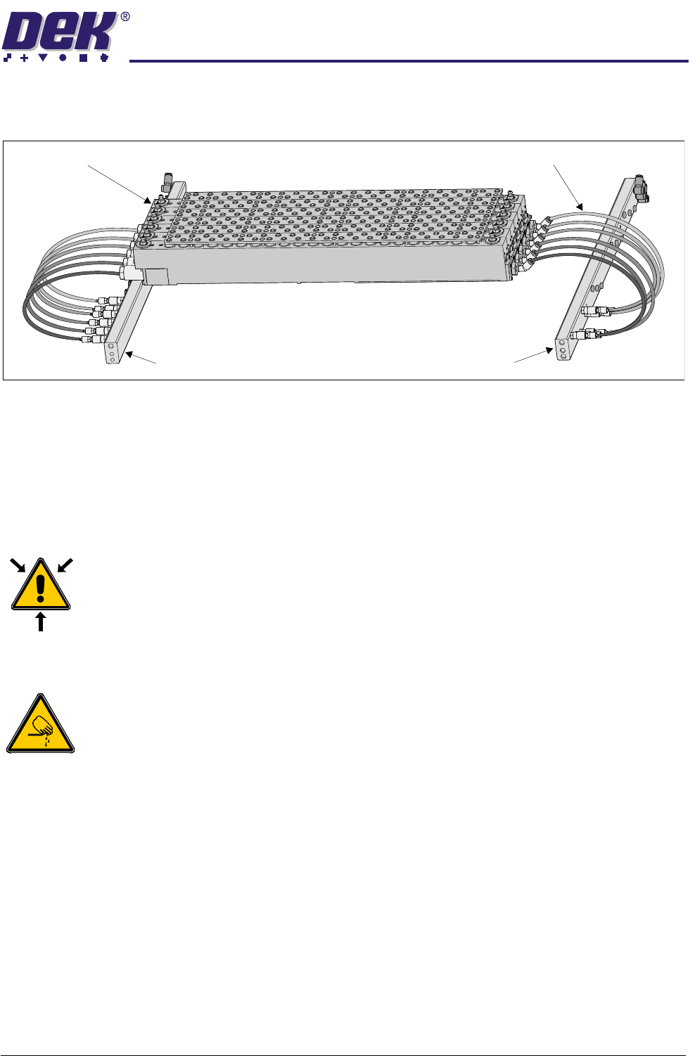
6. Connect 4mm pneumatic tubing from the fluid cut-off valve of the tooling
modules to the override manifold as shown in the figure below.
7. Power up the machine.
8. Carry out FormFlex Pin Pressure procedure in Adjustments and Settings
section of this chapter.
9. Carry out FormFlex Setup in the Machine Programming chapter of this
manual.
Removing FormFlex Tooling
WARNING
COMPRESSED AIR. COMPRESSED AIR SHOULD NEVER IMPINGE UPON THE
BODY. PORTS, PIPES, ETC MUST NEVER BE BLOCKED BY HAND. BEFORE
CONNECTING ANY PNEUMATIC EQUIPMENT TO A COMPRESSED AIR SUPPLY,
ALL MOUNTINGS, FITTINGS, PIPEWORK AND ELECTRICAL CONNECTIONS
SHOULD BE REMOVED FOR SAFETY. NO PIPEWORK ALTERATIONS OR
REMOVAL OF FITTINGS SHOULD BE ATTEMPTED WITH AIR SUPPLIES
CONNECTED.
WARNING
BOARD CLAMPS. EXTREME CARE MUST BE EXERCISED WHEN WORKING IN
THE TOOLING AREA OF THE MACHINE TO AVOID INJURY. THE FOILS ON THE
FRONT AND REAR BOARD CLAMPS ARE VERY SHARP.
1. Gain access to the manual tooling plate.
2. Power down the machine.
3. Disconnect and remove the 4mm pneumatic tubing from the sequencing
manifold to the tooling modules.
4. Disconnect and remove the 4mm pneumatic tubing from the override man-
ifold to the tooling modules.
5. Remove the tooling modules from the manual tooling plate.
Override Manifold
Tooling Modules
Sequencing Manifold
4mm Pneumatic Tubing
1.12 FormFlex Tooling Manual Chapter Issue 4 Jun 04
TECHNICAL REFERENCE
FAULT FINDING
FAULT FINDING
Fault Analysis
WARNING
BOARD CLAMPS. EXTREME CARE MUST BE EXERCISED WHEN WORKING IN
THE TOOLING AREA OF THE MACHINE TO AVOID INJURY. THE FOILS ON THE
FRONT AND REAR BOARD CLAMPS ARE VERY SHARP.
WARNING
COMPRESSED AIR. COMPRESSED AIR SHOULD NEVER IMPINGE UPON THE
BODY. PORTS, PIPES, ETC MUST NEVER BE BLOCKED BY HAND. BEFORE
CONNECTING ANY PNEUMATIC EQUIPMENT TO A COMPRESSED AIR SUPPLY,
ALL MOUNTINGS, FITTINGS, PIPEWORK AND ELECTRICAL CONNECTIONS
SHOULD BE REMOVED FOR SAFETY. NO PIPEWORK ALTERATIONS OR
REMOVAL OF FITTINGS SHOULD BE ATTEMPTED WITH AIR SUPPLIES
CONNECTED.
Symptom Possible Causes Possible Solutions
After periods of inactivity,
some pins not being raised in
one or more tooling modules
during initial setup.
Lack of lubrication of pin seals. Carry out Pins Remaining Down later in this
section.
Board not being fully sup-
ported during printing causing
print process issues.
1. Excessive air in tooling module. 1. Carry out Module Air Check later in this
section.
No pins are raised in any tool-
ing module.
1. Failure of machine air supply. 1. Check the air supply reading at the machine
filter regulator assembly.
2. Air leak between machine interface
FormFlex sequencer assembly.
1. Check the connections between the units,
ensuring no air leaks are present.
When FormFlex is reset,
some FormFlex pins in a mod-
ule remain raised.
1. Sticky FormFlex pins. 1. Carry out Pins Remaining Up later in this
section.
2. Sticky fluid cut-off valve. 1. Carry out Pins Remaining Up later in this
section.
3. Insufficient vacuum. 1. Check the connections between the units,
ensuring no air leaks present.
2. Check air supply to venturi vacuum unit on the
FormFlex sequencer assembly. If air present,
reject the FormFlex sequencer assembly.
All pins not being raised in one
tooling module.
1. Air leak between sequencer mani-
fold and tooling module.
1. Check the connections between the units,
ensuring no air leaks present.
2. Supply pipe to tooling module incor-
rectly connected.
1. Check for correct pipe connections between
the sequencer manifold and tooling module.
2. Confirm pipe connections by disconnecting
the supply pipe to the tooling module at the
module. Press the operator button, air should
escape from the pipe at the relevant point in the
setup sequence.
3. Sticky FormFlex pins. 1. If no fault found, carry out Pins Remaining
Down later in this section.
2. If pins fail to rise, contact DEK Customer
Support.
Excessive oil found leaking
from tooling module.
1. Contact DEK Customer Support.
TECHNICAL REFERENCE
FAULT FINDING
Chapter Issue 4 Jun 04 FormFlex Tooling Manual 1.13
NOTE
1. The following procedures:
• FormFlex Pin Pressure
• Exercise Procedure - Pins Remaining Up
• Exercise Procedure - Pins Remaining Down
• Module Air Check
• Preventive Maintenance Tasks
are the only authorised maintenance tasks that may be carried out.
2. There are no serviceable user parts fitted to the tooling module.
Exercise
Procedure
WARNING
HARMFUL SUBSTANCES. CLEANING WIPES AND CLEANING SOLUTIONS MAY
CONTAIN SUBSTANCES HAZARDOUS TO HEALTH. OBSERVE ALL
MANUFACTURERS’ HEALTH AND SAFETY GUIDELINES. ALWAYS WEAR
APPROVED PROTECTIVE CLOTHING WHEN CLEANING THE MACHINE.
WARNING
BOARD CLAMPS. EXTREME CARE MUST BE EXERCISED WHEN WORKING IN
THE TOOLING AREA OF THE MACHINE TO AVOID INJURY. THE FOILS ON THE
FRONT AND REAR BOARD CLAMPS ARE VERY SHARP.
Pins Remaining Up Carry out this procedure if during reset, some FormFlex pins do not lower in one
or more tooling modules.
1. Open the printhead cover.
2. Press the black exercise button to cycle the pins and fluid cut-off valves of
the tooling modules.
3. The exercise procedure will raise and lower the pins 5 times.
4. During a pins down cycle, light pressure may be applied to the pins that
remain up.
5. Repeat Steps 2 to 4 until all pins are moving freely.
6. If one or more pins remain raised after this procedure, replace the tooling
module.
Pins Remaining
Down
Carry out this procedure if during setup, some FormFlex pins do not raise in one
or more tooling modules.
1. Gain access to the manual tooling plate.
2. Press the amber operator button on the machine front cover.