Formflex Manual.pdf - 第24页
MACHINE PROGRA MMING FORMF LE X SET UP Chapter Issue 4 Jun 04 FormFlex Tooling M anual 2.1 CHAPTER 2 MACHINE PROGRAMMING FORMFLEX SETUP Setup Procedure W ARNIN G BOARD CLAMPS. EXTREM E CARE MUST BE EXERCISED WHEN WORKI N…

1.16 FormFlex Tooling Manual Chapter Issue 4 Jun 04
TECHNICAL REFERENCE
PREVENTIVE MAINTENANCE
Material Safety Data Sheet
Material Safety Data Sheets (MSDS) listing the health and safety aspects
applicable to consumables such as cleaning materials, oils and greases are
available on request from the purchase source.
If difficulty is experienced in obtaining any MSDS, assistance is available from
DEK.
Contact your local DEK agent.
Disposal of Waste Materials
All waste materials including fluids and contaminated materials must be dis-
posed of in accordance with current federal regulations and local state legisla-
tion.
MACHINE PROGRAMMING
FORMFLEX SETUP
Chapter Issue 4 Jun 04 FormFlex Tooling Manual 2.1
CHAPTER 2 MACHINE PROGRAMMING
FORMFLEX SETUP
Setup Procedure
WARNING
BOARD CLAMPS. EXTREME CARE MUST BE EXERCISED WHEN WORKING IN
THE TOOLING AREA OF THE MACHINE TO AVOID INJURY. THE FOILS ON THE
FRONT AND REAR BOARD CLAMPS ARE VERY SHARP.
CAUTION
BOARD CLAMPS.
Care must be taken to ensure that the board clamps are
not damaged when removing or replacing tooling.
The FormFlex setup procedure is only required when setting up the machine for
a new product.
If FormFlex tooling array is not fitted to the machine see ‘Fitting FormFlex
Tooling’ in the Replacement Procedures of the previous chapter and the Form-
Flex Best Working Practices (BWP) Manual for preparation.
If FormFlex tooling array is fitted to the machine carry out the following:
1. Complete the relevant machine setup procedures:
• Power Up and Log On
• Loading a Product File
• Editing a Product File
• Fit Squeegees/ProFlow
NOTE
a. When using FormFlex, the print gap in the product file must be set to zero.
b. If the machine has a fixed head, the Raise Head function button is
replaced by Open Cover function button.
2. If FormFlex has been setup for a previous product, carry out Resetting
FormFlex procedure later in this chapter and refer to the BWP for prepara-
tion details.
3. Select Show Classic from the Instinctiv screen, 700 series only.
4. Select Setup (F6).
5. Select Change Screen (F5). The message ‘Open Front Cover and
Remove Screen ’ is displayed.
6. Raise the front printhead cover/shutter and remove the screen if fitted.
7. Lower the front printhead cover/shutter and select the System button.
Run Head
Paste
Load
Clean
Screen
Adjust Setup Monitor Maint.
Mode
Load
Data
Edit
Data
Setup
Squeegee
Change
Screen
Change
Tooling
Change
Language
Exit
2.2 FormFlex Tooling Manual Chapter Issue 4 Jun 04
MACHINE PROGRAMMING
FORMFLEX SETUP
8. Select Change Screen (F5).
9. Select Change Tooling (F6).
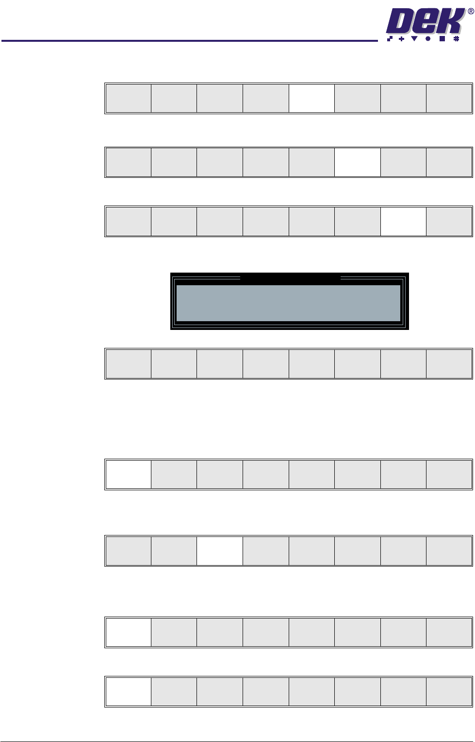
10.Select Generic Tooling (F7).
The following window and menu bar are displayed:
NOTE
If contaminated squeegees are fitted, these should be removed at this point.
11. Select Continue (F1). The print carriage travels to the rear of the machine
and the following message is displayed ‘Table at Home Height’.
12.Select Transprt Height (F3), the message ‘Table at Transport Height’ is
displayed.
13.Place a board at the input sensor of the upline conveyor.
14.Select Load (F1).
15.Select Auto Board (F1).
Mode
Load
Data
Edit
Data
Setup
Squeegee
Change
Screen
Change
Too lin g
Change
Language
Exit
Mode
Load
Data
Edit
Data
Setup
Squeegee
Change
Screen
Change
Tooling
Change
Language
Exit
Adjust
Raise
Head
Remove
Cleaner
Board
Stop
Full
Width
Load
Width
Generic
Tooling
Exit
Generic Tooling Warning
WARNING Paste may drip into the machine
Remove Squeegees NOW
Continue
Open
Cover
No
Continue
Open
Cover
No
Load
Transprt
Height
Board
Clamp
Change
Screen
Raise
Head
Exit
Load
Vision
Height
Home
Height
Board
Clamp
Change
Screen
Raise
Head
Exit
Auto
Board
Manual
Board
Exit