Formflex Manual.pdf - 第28页
MACHINE PROGRA MMING FORMF LE X SET UP Chapter Issue 4 Jun 04 FormFlex Tooling M anual 2.5 26. Press the amber operat or button on the machine fr ont cover . 27. The opera tor button flas hes amber during set up. W ait u…
2.4 FormFlex Tooling Manual Chapter Issue 4 Jun 04
MACHINE PROGRAMMING
FORMFLEX SETUP
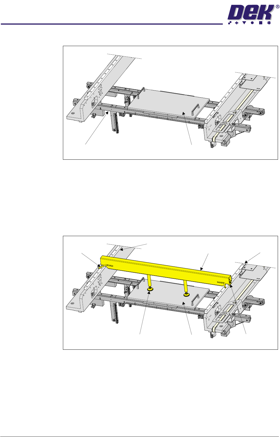
21.Place the FormFlex setup plate centrally over the tooling modules and rails.
22.Before fitting the downhold mechanism, ensure that both;
a. locking levers are in the unlocked position (both levers pointing towards
the centre of the downhold mechanism) and
b. downhold feet are screwed in (clockwise), unless preset in production.
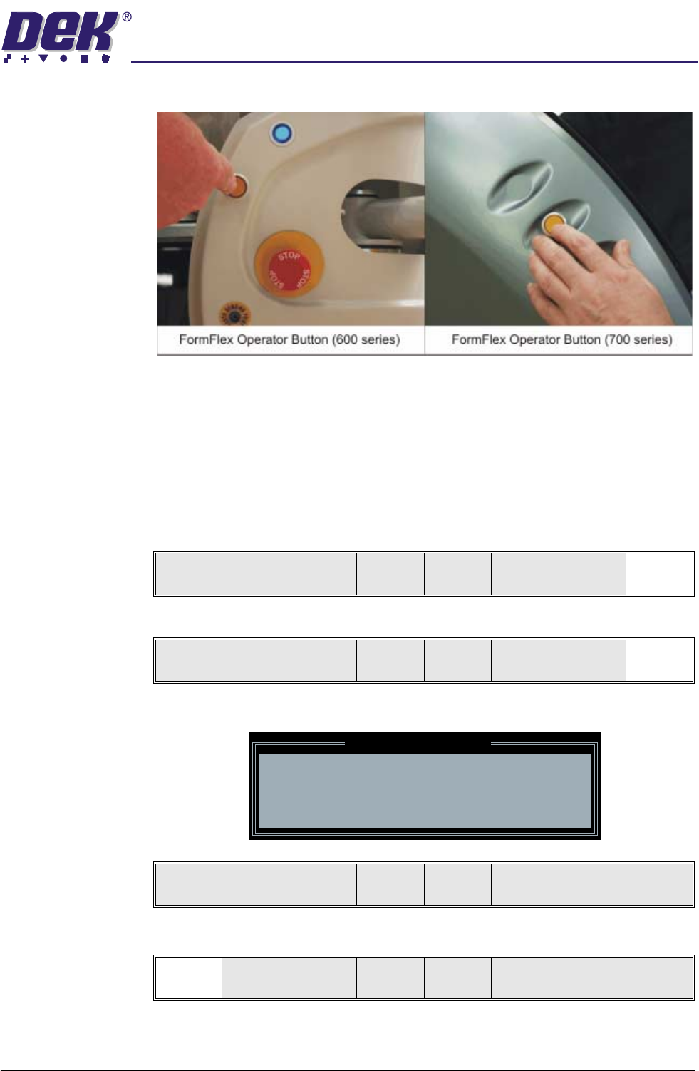
23.Place the downhold mechanism centrally (in the X direction) over the setup
plate with the locking mechanisms fitted over the left and right linear guide
rails.
24.Operate both locking levers outwards from the centre of the downhold
mechanism, clamping the downhold mechanism to the linear guide rails.
25.Screw both downhold feet down onto the setup plate, hand tight, unless
preset in production.
Transport Rails Setup Plate
Left Linear
Guide Rail
Right Linear
Guide Rail
Downhold
Mechanism
Locking Lever
(in 2 positions)
Setup PlateDownhold Feet
Locking Mechanism
(in 2 positions)
MACHINE PROGRAMMING
FORMFLEX SETUP
Chapter Issue 4 Jun 04 FormFlex Tooling Manual 2.5
26.Press the amber operator button on the machine front cover.
27.The operator button flashes amber during setup. Wait until the operator
button displays continuous amber to indicate that the setup is complete.
28.Remove the downhold mechanism and the FormFlex setup plate from the
tooling area.
29.Close the front printhead cover.
30.Press the System button.
31.Select Exit (F8).
32.Select Exit (F8).
The following window and menu bar is displayed:
33.Select Continue (F1).
Exit
Vision
Height
Raise
Head
Exit
Leaving Generic Tooling
WARNING You are about to return
to the Setup Page
Clear all tooling setup
equipment before proceeding
Continue Cancel
Continue Cancel
2.6 FormFlex Tooling Manual Chapter Issue 4 Jun 04
MACHINE PROGRAMMING
FORMFLEX SETUP
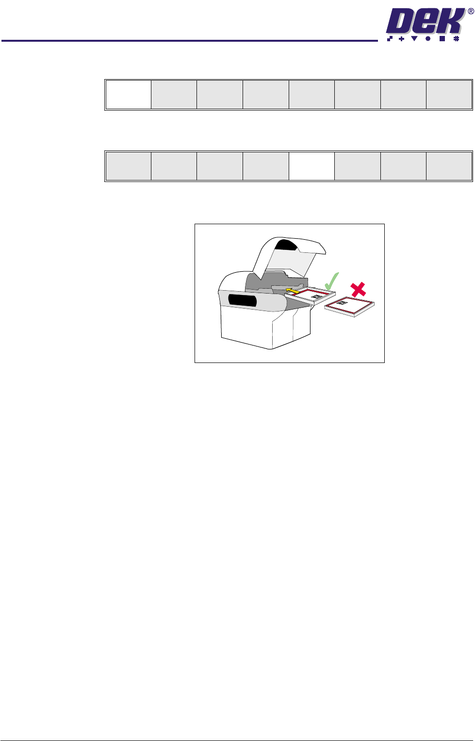
34.Select Auto Board (F1).
35.Remove the board from the rails and select Change Screen (F5).
36.Raise the front printhead cover/shutter.
37.Ensuring correct orientation, fit the correct screen for the product loaded.
NOTE
If squeegees were removed in Step 9, these are to be refitted at this point.
38.Lower the front printhead cover/shutter.
39.Press the System button.
40.The FormFlex setup is now complete.
Auto
Board
Manual
Board
Mode
Load
Data
Edit
Data
Setup
Squeegee
Change
Screen
Change
Too lin g
Change
Language
Exit