Formflex Manual.pdf - 第9页
1.2 FormFlex Tooling Manual Chapter Issue 4 Jun 04 TECHNIC AL RE FERENCE OVERVIEW Figure 1- 2 Location of Element s (700 series) FormFlex tooli ng is a fully automated tooling faci lity that conforms to any given board p…
TECHNICAL REFERENCE
OVERVIEW
Chapter Issue 4 Jun 04 FormFlex Tooling Manual 1.1
CHAPTER 1 TECHNICAL REFERENCE
OVERVIEW
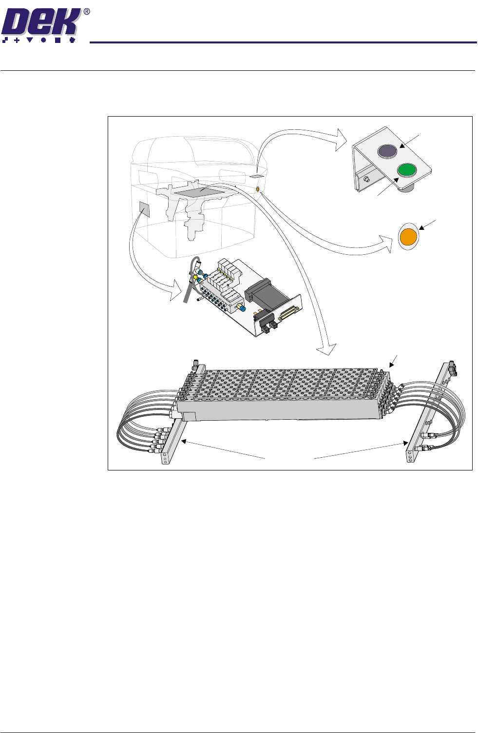
Figure 1-1 Location of Elements (600 series)
Operator Interface
Tooling Modules
Manifolds
FormFlex Sequencer Assembly
Reset Button
(green)
Exercise Button
(black)
Operator Button
(amber)
1.2 FormFlex Tooling Manual Chapter Issue 4 Jun 04
TECHNICAL REFERENCE
OVERVIEW
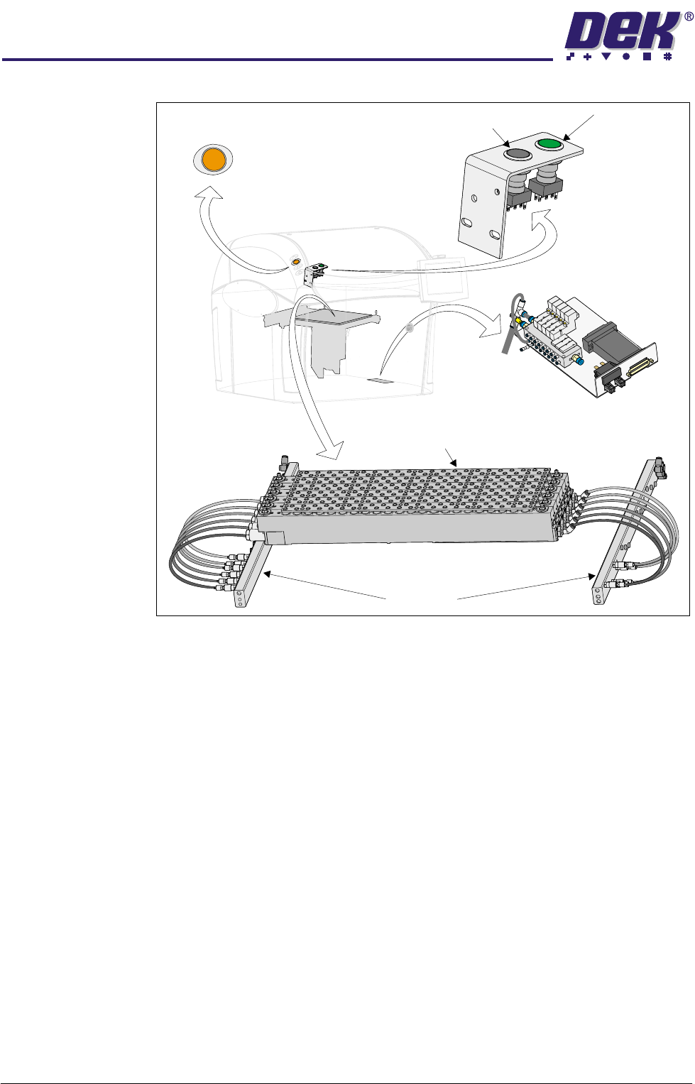
Figure 1-2 Location of Elements (700 series)
FormFlex tooling is a fully automated tooling facility that conforms to any given
board profile, fully supporting the underside of a populated board and the
stencil.
The standard Formflex tooling system configuration of six tooling modules can
be configured to handle the following board sizes:
• Minimum board size - 38mm x 50mm
• Maximum board size - 254mm x 508mm
• Board thickness - 0.4mm - 5.0mm
FormFlex tooling array consists of 6 tooling modules, each module containing
44 pins in two rows. The FormFlex array is held magnetically to the manual
tooling plate. The FormFlex tooling height is 81mm standard tooling height, with
a maximum component under board clearance of 15mm.
With the board loaded and raised to print height, all the FormFlex pins are
extended using hydraulic fluid pressure until they meet the underside of the
board, stencil or component. The pins remain in this position supported by the
reservoir of hydraulic fluid until the system is reset.
Once the tooling has conformed to the board profile, any force exerted on the
pins, in a tooling module, is caused by differences in board profile. Variations
Operator Interface
Tooling Modules
Manifolds
Operator Button
(amber)
Exercise Button
(black)
Reset Button
(green)
FormFlex Sequencer Assembly
TECHNICAL REFERENCE
OVERVIEW
Chapter Issue 4 Jun 04 FormFlex Tooling Manual 1.3
in board layout, component tolerances or board misalignment can cause the
pins to displace. The resultant force on the pins is spread across all unaffected
pins in the tooling module raising them proportionally to the downward force.
The system therefore self compensates for any anomalies in board profile
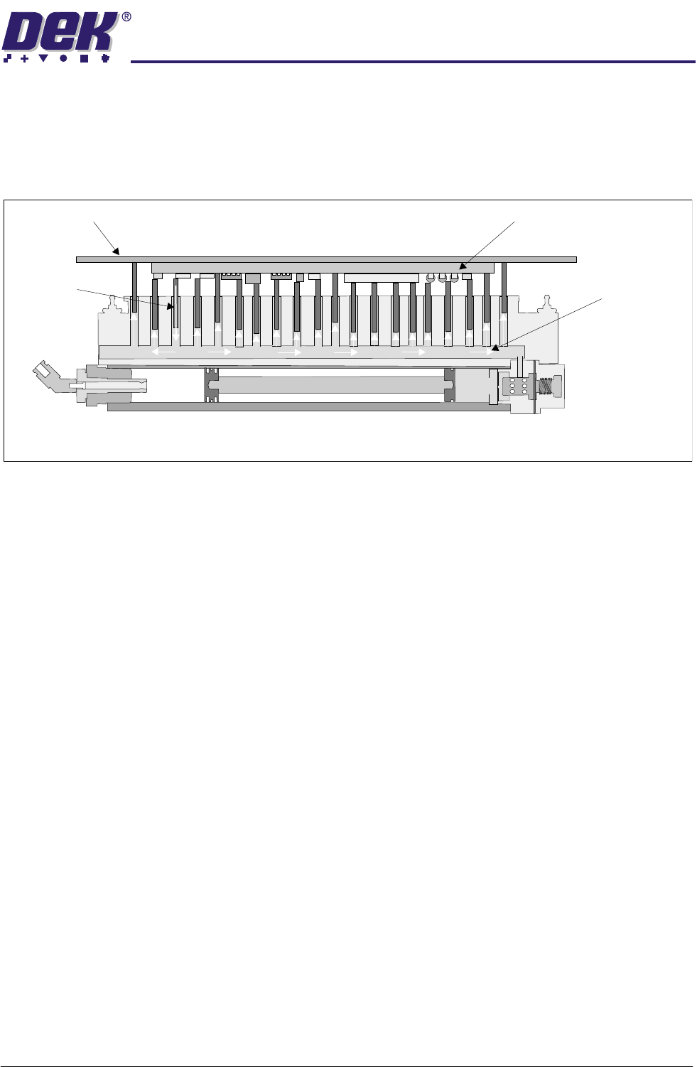
without detriment to overall board or component support, figure below refers.
Figure 1-3 FormFlex Pin Displacement
Three of the solenoid valves on the FormFlex sequencer are used to control up
to 15 tooling modules. The solenoid valves are controlled by the M34 control
pod, mounted on the FormFlex sequencer assembly, which operates each
solenoid valve in turn with a 20 second delay allowing all the FormFlex pins on
one set of tooling modules to be raised before the next set is activated.
PCB Component Variation Causing One FormFlex Pin to Displace
FormFlex Pin
Displaced
Stencil
Force Being Dissipated
Over All Other Pins
PCB and Components