stopper for HF-series for processing area 1.pdf - 第17页
SIPLACE 1 Assembly instructions Special design Stopper for placement area 1 (00166322-01) SIPLACE HF-series 06/2007 Edition 17 : Reinsta ll all removed covers and the removed lifting t ables. : Fix the cables with ca ble…
1 Assembly instructions Special design Stopper for placement area 1 (00166322-01) SIPLACE HF-series SIPLACE
06/2007 Edition
16
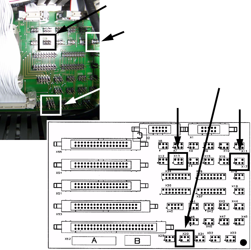
: Plug in the cables at the right sockets by comparing the label on the plugs and the sockets.
See layout below for details.
1
1
1
1
1
1
1
1
1
X 17
X 30
X 13
X 13
X 17
X 30
SIPLACE 1 Assembly instructions Special design Stopper for placement area 1 (00166322-01) SIPLACE HF-series
06/2007 Edition
17
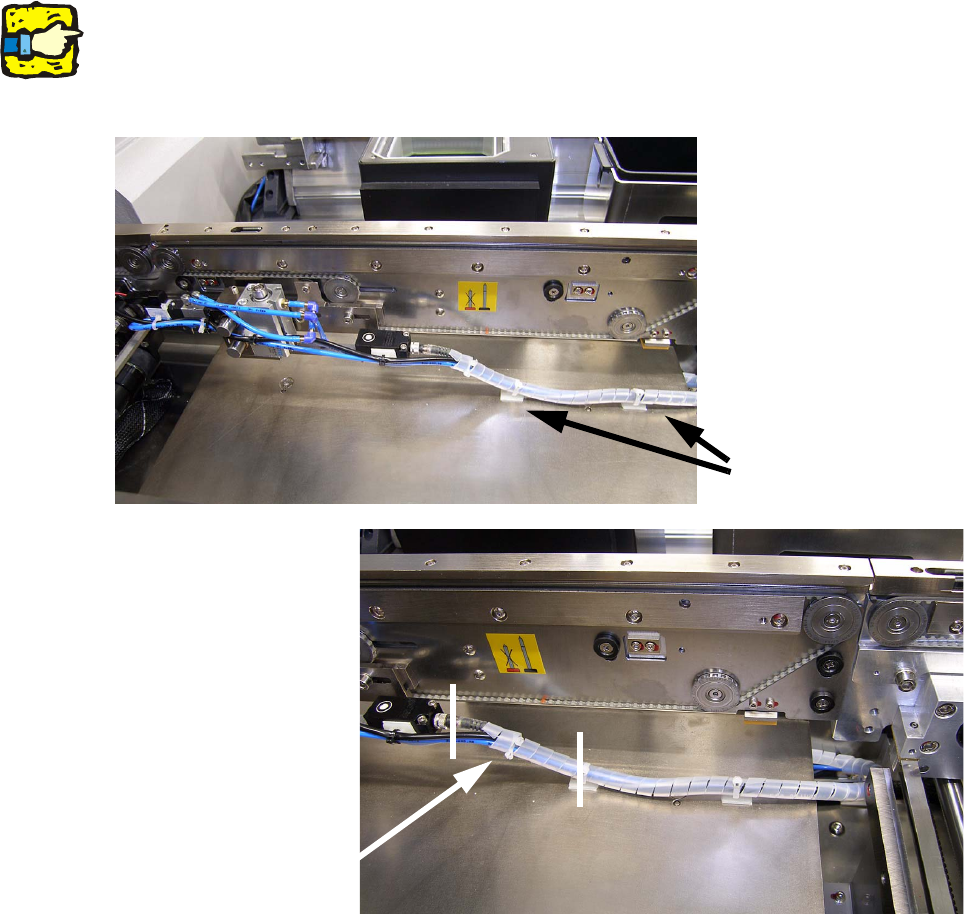
: Reinstall all removed covers and the removed lifting tables.
: Fix the cables with cable pads and cable ties to the lifting table.
1
Make sure that the cables between the module and the first pad are long enough to allow the lifting
table to move up and down without damaging the cables! 1
1
1
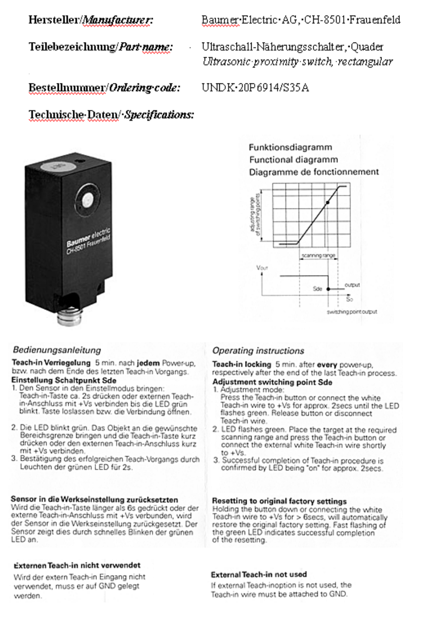
1.8 Setting the sonar sensor
To set the sonar sensor, follow the manufacturer’s manual when the stopper is installed. 1
Run the customer’s PCB on the conveyor belt over the sonar sensor and teach it as per the in-
structions. 1
Cable pads
Cables must be
long enough
1 Assembly instructions Special design Stopper for placement area 1 (00166322-01) SIPLACE HF-series SIPLACE
06/2007 Edition
18
1