stopper for HF-series for processing area 1.pdf - 第9页
SIPLACE 1 Assembly instructions Special design Stopper for placement area 1 (00166322-01) SIPLACE HF-series 06/2007 Edition 9 : Remove the marked screws and the spacers. 1 1 Marked sc rews Marked scre ws
1 Assembly instructions Special design Stopper for placement area 1 (00166322-01) SIPLACE HF-series SIPLACE
06/2007 Edition
8
1.7 Hardware installation
: Shut down the machine and switch of the main switch.
: Disconnect the power and the air supply before start working at the machine.
1.7.1 Mounting the stopper module on the conveyor
: Unscrew the two lifting tables and remove them from the conveyor.
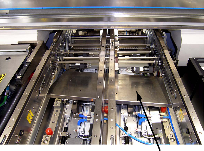
: Unscrew the metal cover and remove it from the machine.
1
1
1
1
1
1
Metal cover
SIPLACE 1 Assembly instructions Special design Stopper for placement area 1 (00166322-01) SIPLACE HF-series
06/2007 Edition
9
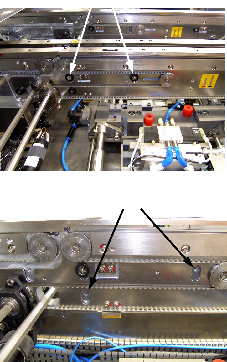
: Remove the marked screws and the spacers.
1
1
Marked screws
Marked screws
1 Assembly instructions Special design Stopper for placement area 1 (00166322-01) SIPLACE HF-series SIPLACE
06/2007 Edition
10
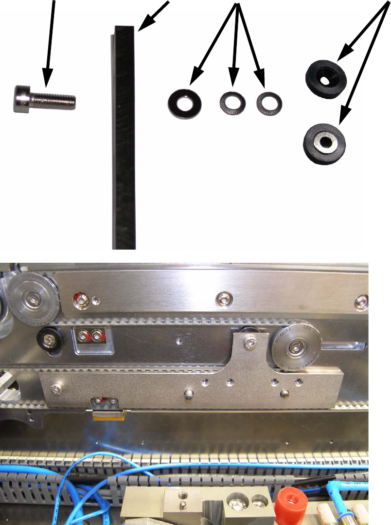
: To mount the adapter to the conveyor, use the delivered screws, shims and the removed spa-
cers like shown on the pictures below. Assemble the parts in the same order like on the picture
below, the spacer has to be fitted the same way it was originally.
If you don’t use the shims, the clamping system won’t work properly!
1
Screw
Adapter
Shims
Spacer