SIPLACE-SX4-DX4-用户手册.pdf - 第107页
Service Work 3.6.6 Replacing the Cylinder Unit on the Adjustmen t Unit (DC/QC only) Conveyor Service Manual SIPLACE SX4/DX4 107 ► Loosen the screws fastening the cylinder unit to the carriage a n d then remove the carria…
Service Work
Conveyor 3.6.6 Replacing the Cylinder Unit on the Adjustment Unit (DC/QC only)
106 Service Manual SIPLACE SX4/DX4
3.6.6
3.6.6 Replacing the Cylinder Unit on the Adjustment Unit (DC/QC only)
Replacing the Cylinder Unit on the Adjustment Unit (DC/QC only)
Parts, equipment and tools
There are two versions of the cylinder unit, one for the adjustment unit in the input area or center and
one for the adjustment unit in the output area.
▪ Adjustment unit 1 for width adjustment DC split (incl. trailing cable) – input area/center [03081359-xx]
▪ Adjustment unit 2 for width adjustment DC split (incl. trailing cable) – output area [03081361-xx]
Overview
Removal
► Use the software to move the conveyor sides into the position which allows you best access.
► If required, loosen the conveyor side clamps. (see "3.6.1 Loosening the Conveyor Side Clamps"
[➙95]).
► Switch off the machine, disconnect it from the power supply and secure it to prevent unauthorized
reactivation. Observe the instructions in section "1.2 Preparatory Work..." [ ➙ 12].
► Loosen the screws fastening the lifting table plate and remove the lifting table plate.
► Dismantle the cover plate on the lower end of the trailing cable, to gain access to the cable.
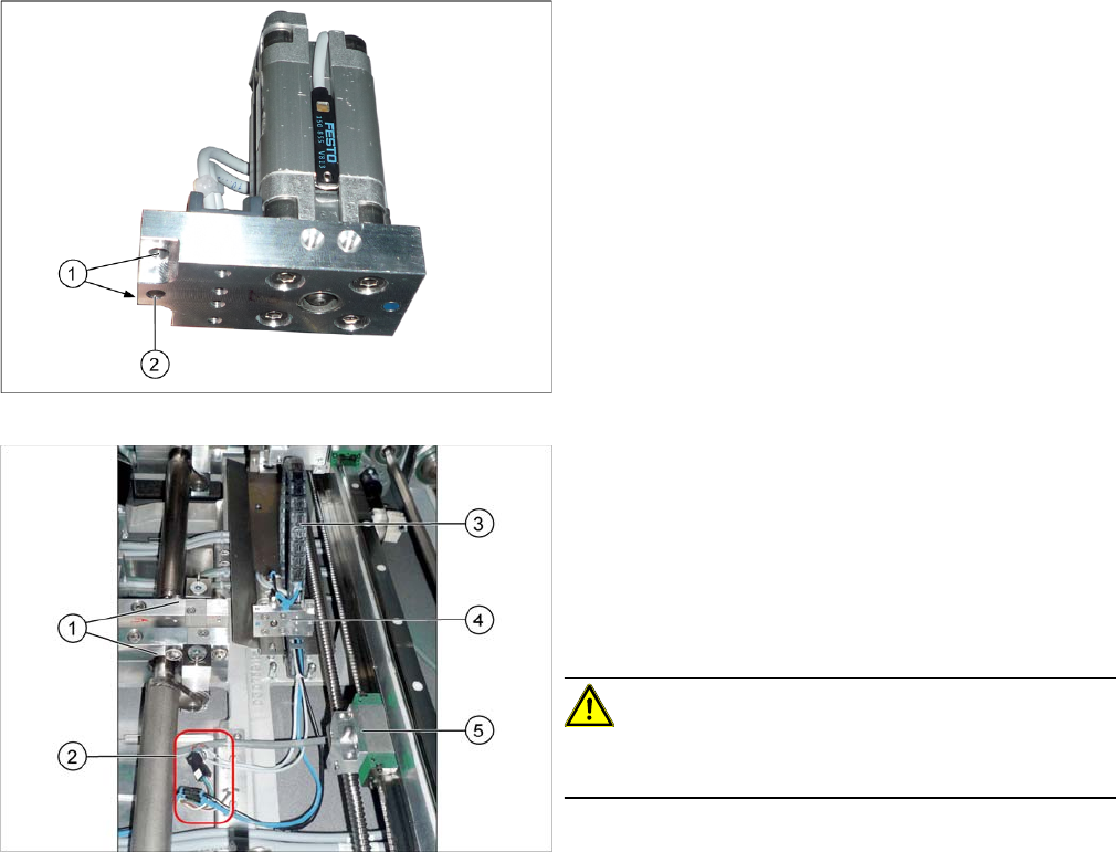
Cylinder unit
1. Holes for the carriage fastening screws
2. Centering hole
1. Lifting tables
2. Electrical and pneumatic connections for the cylinder
unit
3. Trailing cable for the cylinder unit
4. Cylinder unit
5. Guide carriage with receptacle for cylinder unit and
centering pin
CAUTION!
Never dismantle the carriage or the receptacle for the cyl-
inder unit!
Service Work
3.6.6 Replacing the Cylinder Unit on the Adjustment Unit (DC/QC only) Conveyor
Service Manual SIPLACE SX4/DX4 107
► Loosen the screws fastening the cylinder unit to the carriage and then remove the carriage. The cyl-
inder unit is pinned and can be stiff to move.
► Unplug the electrical and pneumatic connections. You may want to mark the positions, to make clear
assignment easier later on. Open the corresponding cable ties to help you, if needed.
► Remove the cylinder unit from the machine.
Installation
► Follow the removal instructions in reverse order for installation. Also observe the following instruc-
tions:
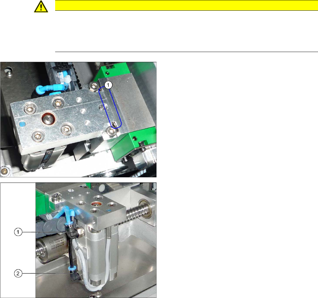
CAUTION
Installation instructions
► Make sure that the cylinder unit is flush against the guide carriage (see below).
► Make sure that the cables and hoses do not rub against any parts.
► Make sure that you have correctly assigned the hoses to the connections (see below).
1. The cylinder unit must lie flush against the carriage.
1. Connection "Move cylinder in" – blue hose
2. Connection "Move cylinder out" – black hose
Service Work
Conveyor 3.6.7 Replacing the Short-Stroke Cylinder on the Adjustment Unit [00356862-xx]
108 Service Manual SIPLACE SX4/DX4
3.6.7
3.6.7 Replacing the Short-Stroke Cylinder on the Adjustment Unit [00356862-xx] (DC/QC only)
Replacing the Short-Stroke Cylinder on the Adjustment Unit [00356862-xx] (DC/QC
only)
Parts, equipment and tools
▪ Short-stroke cylinder ADVU-16-20-P-A-SA [00356862-xx]
Overview
Removal
► Loosen the conveyor side clamps. (see "3.6.1 Loosening the Conveyor Side Clamps" [ ➙ 95]).
► Switch off the machine, disconnect it from the power supply and secure it to prevent unauthorized
reactivation. Observe the instructions in section "1.2 Preparatory Work..." [ ➙ 12].
► Remove the cylinder unit from the machine. (See "3.6.6 Replacing the Cylinder Unit on the Adjust-
ment Unit (DC/QC only)" [ ➙ 106])
► Remove the cylinder switch from the short-stroke cylinder. Mark their positions, to make clear as-
signment easier later on.
► Unplug the two pneumatic connections to the short-stroke cylinder. Mark their positions, to make
clear assignment easier later on.
► Loosen the screws fastening the short-stroke cylinder and remove it from the cylinder unit.
Installation
► Follow the removal instructions in reverse order for installation. Also observe the following instruc-
tions:
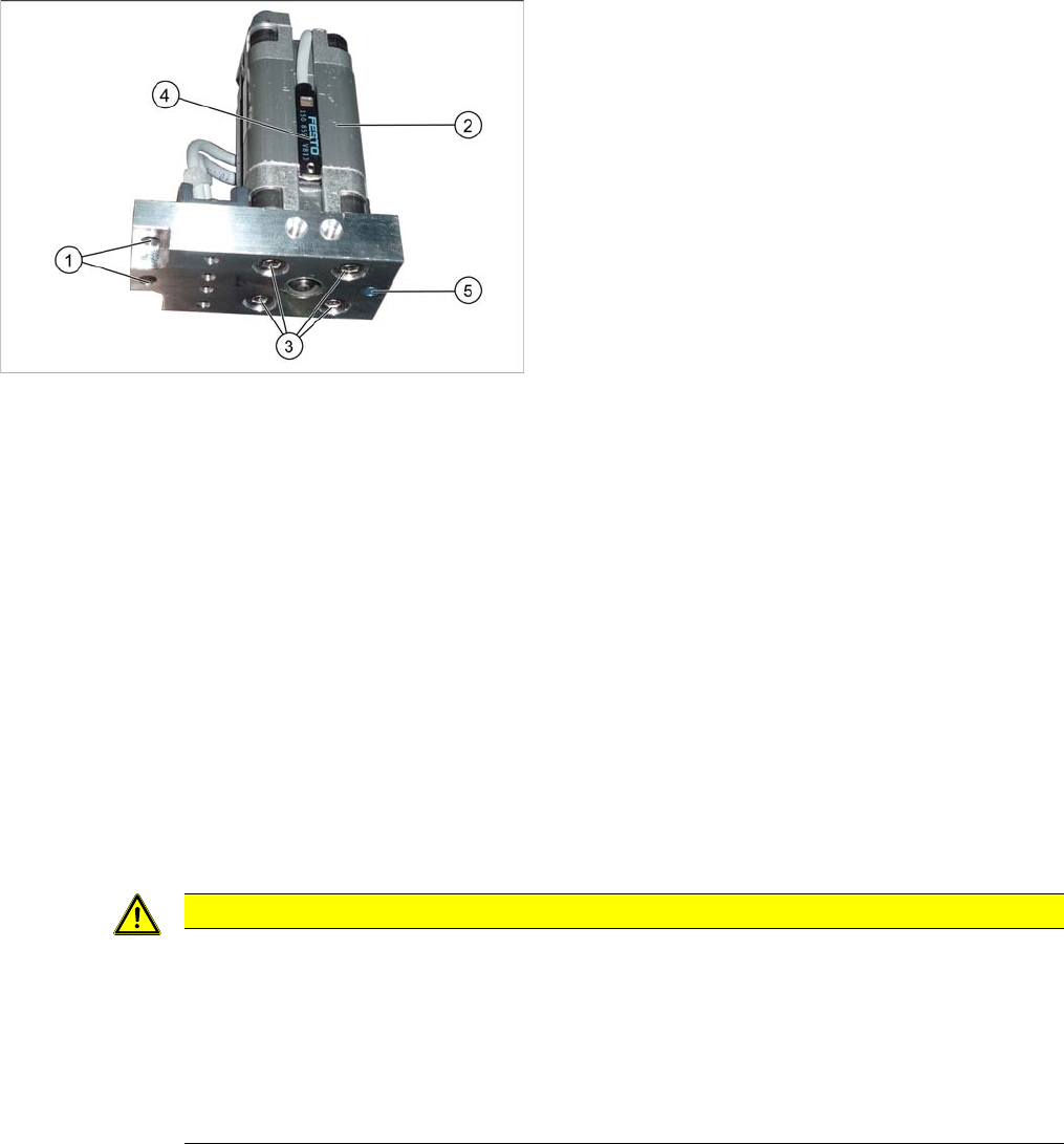
1. Holes for the carriage fastening screws
2. Pneumatic cylinder
3. Screws fastening the cylinder unit
4. Cylinder switch on the adjustment unit [03077361-xx]
5. Proximity switch [00304908-xx]
CAUTION
Installation instructions
► Fit the cylinder switch which you removed from the old short-stroke cylinder into the new
one. Use the same cylinder switch position as was used in the old short-stroke cylinder.
► Make sure that the cylinder unit is flush against the carriage. (See also "3.6.6 Replacing the
Cylinder Unit on the Adjustment Unit (DC/QC only)" [ ➙ 106])
► Make sure that you connect the hoses correctly. (See also "3.6.6 Replacing the Cylinder
Unit on the Adjustment Unit (DC/QC only)" [ ➙ 106])