SIPLACE-SX4-DX4-用户手册.pdf - 第117页
Service Work 3.6.13 Replacing the Width Adjustment Drive [03078341-xx] Conveyor Service Manual SIPLACE SX4/DX4 117 3.6.13 3 . 6 . 1 3 R e p la c in g t h e W id t h A d ju s t m e n t D r iv e [ 0 3 0 7 8 3 4 1 - x x ] R…
Service Work
Conveyor 3.6.12 Replacing the Width Adjustment Valve [03077072-xx]
116 Service Manual SIPLACE SX4/DX4
3.6.12
3.6.12 Replacing the Width Adjustment Valve [03077072-xx]
Replacing the Width Adjustment Valve [03077072-xx]
Parts, equipment and tools
▪ SMC valve assembly [03077072-xx]
Overview
Removal
► Use the software to move the conveyor sides into the position which allows you best access. As an
alternative, you can loosen the clamps for the relevant sides in dual conveyors.
► Switch off the machine, disconnect it from the power supply and secure it to prevent unauthorized
reactivation. Observe the instructions in section "1.2 Preparatory Work..." [ ➙ 12].
► Loosen the screws fastening the cover on the conveyor control at location 4 and remove this cover.
► Unplug the pneumatic and electrical connections for the relevant solenoid valve. You may want to
mark the positions, to make clear assignment easier later on.
► Remove the solenoid valve from the machine.
Installation
► Follow the removal instructions in reverse order for installation. Also observe the following instruc-
tions:
See also
3.6.1 Loosening the Conveyor Side Clamps [ ➙ 95]
3.6.1 Loosening the Conveyor Side Clamps [ ➙ 95]
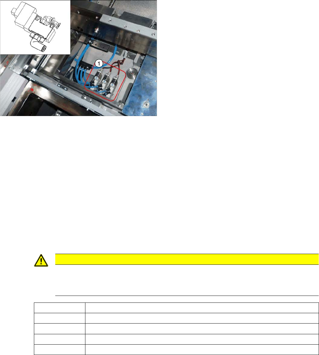
1. Solenoid valves.
The solenoid valves are located in placement area 1
(locations 4) next to the middle adjustment unit.
CAUTION
Installation instructions
► Replace any opened cable ties.
► Make sure that the connections are correct (see the following table).
Connection 1 Compressed air supply (L-quick release fastening QSML-M3-4)
Connection 2 "Move in cylinder" blue hose (L-quick release fastening QSML-M3-3)
Connection 3 Silencer U-M3
Connection 4 "Move out cylinder" black hose (L quick release fastening QSML-M3-3)
Connection 5 Silencer U-M3
Service Work
3.6.13 Replacing the Width Adjustment Drive [03078341-xx] Conveyor
Service Manual SIPLACE SX4/DX4 117
3.6.13
3.6.13 Replacing the Width Adjustment Drive [03078341-xx]
Replacing the Width Adjustment Drive [03078341-xx]
Parts, equipment and tools
▪ Drive unit for width adjustment [03078341-xx]
▪ Belt tension device (00326015-xx)
▪ Help of second person, if needed
Overview
Removal
► Dismantle the mount with width adjustment drive and, if necessary, the conveyor drive, as described
in "3.6.9 Replacing the Conveyor Drive [03075892-xx]" [ ➙110]. The screws fastening the conveyor
drive do not need to be loosened. Move the adjustment units to one side (as far as location 3 and 4)
and do not move from there if possible. This makes refitting easier later on.
► Loosen the screws fastening the width adjustment drive and remove this drive.
Installation
► Follow the removal instructions in reverse order for installation. Also observe the following instruc-
tions:
See also
5.5.3.2 Setting the Parallelism of the Dual/Quad Conveyor Sides/Adjustment Units [ ➙ 259]
CAUTION
Parallelism
This may affect the parallelism of the width adjustment unit. Bear in mind that this could then
affect the parallelism of the conveyor sides.
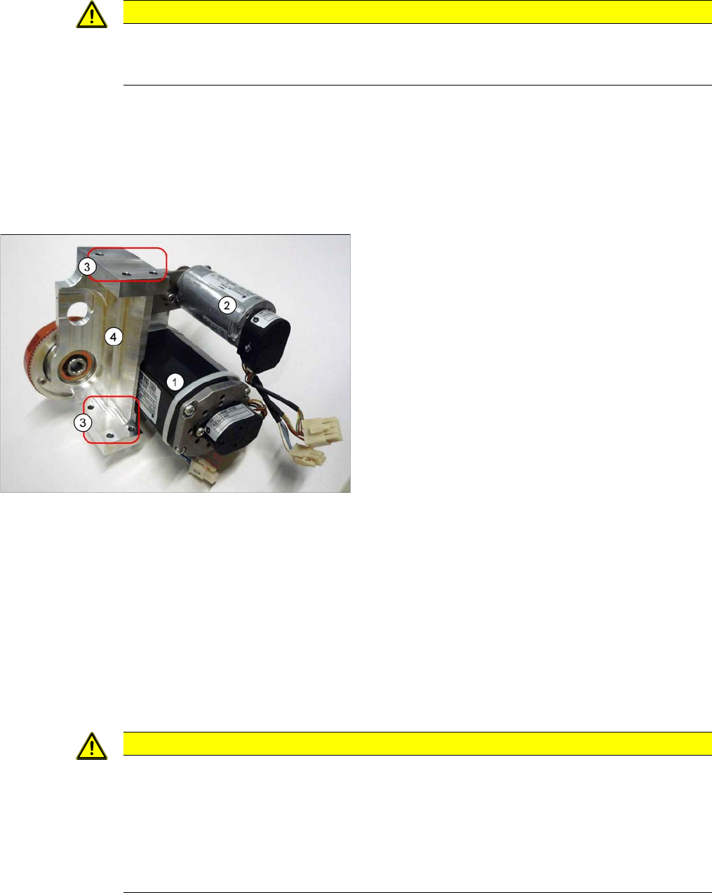
1. Conveyor drive (not for SC)
2. Width adjustment drive
3. Holes for the fastening screws (depends on installa-
tion position)
4. Holes for the fastening screws (depends on installa-
tion position)
CAUTION
Installation instructions
► Make sure that the adjustment units run parallel to one another. To check this, move them
manually to the side, as far as the end stop. The adjustment units should all hit the side at
the same time. Pay close attention to the middle shaft. The distances of the guidance car-
riages to the end of the rail must be the same in all cases.
► Set the tension of the width adjustment toothed belt to 27+/-2 Hz. (See "5.5.1.2 Setting the
Width Adjustment Belt Tension" [ ➙ 252])
Service Work
Conveyor 3.6.14 Replacing the Width Adjustment Toothed Belt [03076223-xx]
118 Service Manual SIPLACE SX4/DX4
3.6.14
3.6.14 Replacing the Width Adjustment Toothed Belt [03076223-xx]
Replacing the Width Adjustment Toothed Belt [03076223-xx]
Parts, equipment and tools
▪ Toothed belt Brecoflex 12 T5/3850 z=770 [03076223-xx]
▪ Belt tension device (00326015-xx)
▪ Help of second person, if needed
Overview
Removal
► Use the software to move the conveyor sides into the position which allows you best access. As an
alternative, you can loosen the clamps for the relevant sides in dual conveyors.
► Switch off the machine, disconnect it from the power supply and secure it to prevent unauthorized
reactivation. Observe the instructions in section "1.2 Preparatory Work..." [ ➙ 12].
► Move the adjustment units to one side (as far as location 3 and 4) and do not move from there if
possible. This makes refitting easier later on.
► Loosen the screw fastening the deflection pulley with slot.
► Unthread the toothed belt and take this out of the machine.
Installation
► Follow the removal instructions in reverse order for installation. Also observe the following instruc-
tions:
See also
3.6.1 Loosening the Conveyor Side Clamps [ ➙ 95]
CAUTION
Parallelism
This may affect the parallelism of the width adjustment unit. Bear in mind that this could then
affect the parallelism of the conveyor sides.
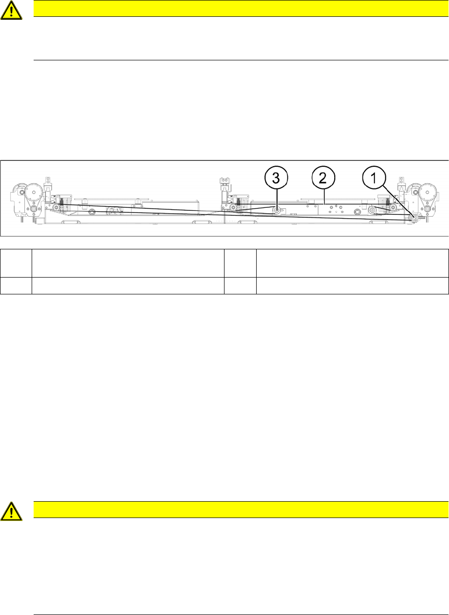
(1) Width adjustment drive (2) Measurement point on width adjustment
toothed belt
(3) Deflection pulley with slot
CAUTION
Installation instructions
► Make sure that the adjustment units run parallel to one another. To check this, move them
manually to the side, as far as the end stop. The adjustment units should all hit the side at
the same time. Pay close attention to the middle shaft. The distances of the guidance car-
riages to the end of the rail must be the same in all cases.
► Set the tension of the width adjustment toothed belt to 27+/-2 Hz. (See "5.5.1.2 Setting the
Width Adjustment Belt Tension" [ ➙ 252])