SIPLACE-SX4-DX4-用户手册.pdf - 第122页
Service Work Conveyor 3.6.18 Replacing the Hexagonal Shaft [03057258-xx] 122 Service Manual SIPLACE SX4/DX4 3.6.18 3 . 6 . 1 8 R e p la c in g t h e H e x a g o n a l S h a f t [ 0 3 0 5 7 2 5 8 - x x ] Replacing the Hex…
Service Work
3.6.17 Replacing the Deflection Pulley Conveyor
Service Manual SIPLACE SX4/DX4 121
3.6.17
3.6.17 Replacing the Deflection Pulley
Replacing the Deflection Pulley
Parts, equipment and tools
▪ Deflection pulley, geared [03063837-xx]
▪ Deflection pulley, ungeared [03063838-xx]
▪ Loctite 241
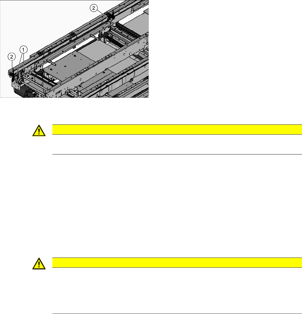
Overview
Removal
► Use the software to move the conveyor sides into the position which allows you best access. As an
alternative, you can loosen the clamps for the relevant sides in dual conveyors.
► Switch off the machine, disconnect it from the power supply and secure it to prevent unauthorized
reactivation. Observe the instructions in section "1.2 Preparatory Work..." [ ➙ 12].
► Loosen the screw fastening the deflection pulley with slot.
► Loosen the fastening screw on the deflection pulley to be replaced.
► Unthread the deflection pulley from the conveyor toothed belt and remove it.
Installation
► Follow the removal instructions in reverse order for installation. Also observe the following instruc-
tions:
See also
3.6.1 Loosening the Conveyor Side Clamps [ ➙ 95]
1. Deflection pulleys, ungeared (4x per side)
2. Deflection pulleys, geared (4x per side)
CAUTION
Toothed belt
► Make sure that the toothed belt is not folded or otherwise damaged.
CAUTION
Installation instructions
► Make sure that the toothed belt is not folded or otherwise damaged.
► After fitting all parts, set the toothed belt tension. (See "5.5.1.1 Setting the Conveyor Belt
Tension" [ ➙ 251])
► Secure with screws with Loctite 241.
Service Work
Conveyor 3.6.18 Replacing the Hexagonal Shaft [03057258-xx]
122 Service Manual SIPLACE SX4/DX4
3.6.18
3.6.18 Replacing the Hexagonal Shaft [03057258-xx]
Replacing the Hexagonal Shaft [03057258-xx]
Parts, equipment and tools
▪ Hexagonal shaft assembly [03057258-xx]
Removal
► Use the software to move the conveyor sides into the position which allows you best access. As an
alternative, you can loosen the clamps for the relevant sides in dual conveyors.
► Switch off the machine, disconnect it from the power supply and secure it to prevent unauthorized
reactivation. Observe the instructions in section "1.2 Preparatory Work..." [ ➙ 12].
Installation
► Follow the removal instructions in reverse order for installation.
See also
3.6.1 Loosening the Conveyor Side Clamps [ ➙ 95]
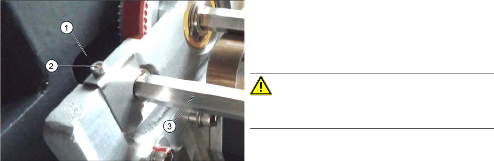
Hexagonal shafts (using example of SX1/SX2)
► Loosen the fastening (2) on the hexagonal shaft (3).
► You can now carefully push one side of the hexago-
nal shaft into the hole in the machine frame (1) and
thread it out of the conveyor sides, together with the
bearing.
CAUTION!
There are cables run inside the machine frame.
Make sure you do not damage these cables.
Service Work
3.6.19 Replacing the Sensor Rail (Stopper) Valve [03077072-xx] Conveyor
Service Manual SIPLACE SX4/DX4 123
3.6.19
3.6.19 Replacing the Sensor Rail (Stopper) Valve [03077072-xx]
Replacing the Sensor Rail (Stopper) Valve [03077072-xx]
Parts, equipment and tools
▪ Sensor rail (stopper) valve [03077072 xx]
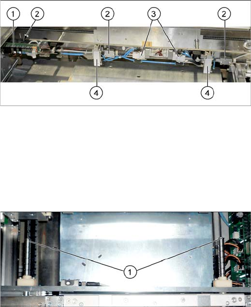
Overview
Removal
► Use the software to move the conveyor sides into the position which allows you best access. As an
alternative, you can loosen the clamps for the relevant sides in dual conveyors.
► Switch off the machine, disconnect it from the power supply and secure it to prevent unauthorized
reactivation. Observe the instructions in section "1.2 Preparatory Work..." [ ➙ 12].
► Dismantle the cover plate on the sensor rail.
► Unplug the electrical and pneumatic connections to the solenoid valve. Mark their positions, to make
clear assignment easier later on.
► Loosen the screws holding the solenoid valve in place and remove the solenoid valve.
1. Conversion board
2. Ultrasonic sensors (3x)
3. Solenoid valves (2x)
4. Stoppers (2x)
► If needed, the sensor rail can be removed to allow
better access. Simply loosen the two screws (1) on
the ends of both shafts.