SIPLACE-SX4-DX4-用户手册.pdf - 第132页
Service Work Conveyor 3.6.23 Replacing the Clamping Plate [03081665- xx] 132 Service Manual SIPLACE SX4/DX4 3.6.23 3 . 6 . 2 3 R e p la c in g t h e C la m p in g P la t e [ 0 3 0 8 1 6 6 5 - x x ] Replacing the Clampi n…
Service Work
3.6.22 Replacing the Conversion Board [03081718-xx] Conveyor
Service Manual SIPLACE SX4/DX4 131
3.6.22
3.6.22 Replacing the Conversion Board [03081718-xx]
Replacing the Conversion Board [03081718-xx]
Parts, equipment and tools
▪ Conversion board assembly [03081718-xx]
Overview
Removal
► Use the software to move the conveyor sides into the position which allows you best access. As an
alternative, you can loosen the clamps for the relevant sides in dual conveyors.
► Switch off the machine, disconnect it from the power supply and secure it to prevent unauthorized
reactivation. Observe the instructions in section "1.2 Preparatory Work..." [ ➙ 12].
► Dismantle the cover plate on the sensor rail.
► Unplug all connections to the conversion board. You may want to mark the positions, to make clear
assignment easier later on.
► Loosen the screws fastening the conversion board and remove it from the machine.
Installation
► Follow the removal instructions in reverse order for installation.
See also
3.6.1 Loosening the Conveyor Side Clamps [ ➙ 95]
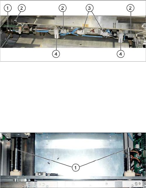
1. Conversion board
2. Ultrasonic sensors (3x)
3. Solenoid valves (2x)
4. Stoppers (2x)
► If needed, the sensor rail can be removed to allow
better access. Simply loosen the two screws (1) on
the ends of both shafts.
Service Work
Conveyor 3.6.23 Replacing the Clamping Plate [03081665-xx]
132 Service Manual SIPLACE SX4/DX4
3.6.23
3.6.23 Replacing the Clamping Plate [03081665-xx]
Replacing the Clamping Plate [03081665-xx]
Parts, equipment and tools
▪ Clamping plate assembly [03081665-xx]
▪ Tool for travel limitation [03013650-xx]
Overview
Removal
► Use the software to move the conveyor sides into the position which allows you best access. As an
alternative, you can loosen the clamps for the relevant sides in dual conveyors.
► Switch off the machine, disconnect it from the power supply and secure it to prevent unauthorized
reactivation. Observe the instructions in section "1.2 Preparatory Work..." [ ➙ 12].
Installation
► Follow the removal instructions in reverse order for installation. Also observe the following instruc-
tions:
See also
3.6.1 Loosening the Conveyor Side Clamps [ ➙ 95]
3.6.24
3.6.24 Replacing the Compression Spring on the Clamping Plate [00364715-xx]
Replacing the Compression Spring on the Clamping Plate [00364715-xx]
Parts, equipment and tools
▪ Compression spring 0.63*5.63*26 [00364715-xx]
▪ Tool for travel limitation [03013650-xx]
Removal/installation
► Removal and installation of the pressure spring is the same as that for the clamping plate. (See
"3.6.23 Replacing the Clamping Plate [03081665-xx]" [ ➙ 132])
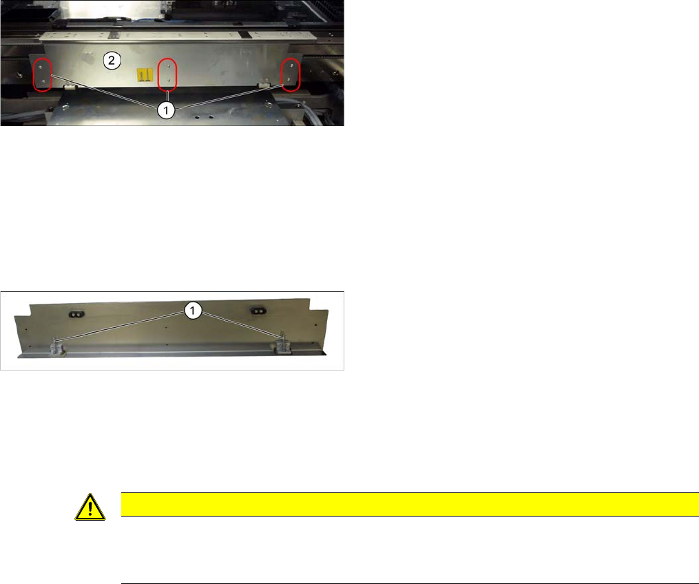
Clamping plate (using example of SX1/SX2)
1. Screws fastening the clamping plate
2. Clamping plate
Clamping plate (using example of SX1/SX2)
► Loosen the 6 screws fastening the clamping plate
and remove the clamping plate. Make sure that you
do not lose the two compression springs (1).
CAUTION
Installation instructions
► Reinsert the compression springs.
► Check the clamping plate for ease of movement.
Service Work
3.6.25 Replacing the Conveyor Control TSP410 [03076208-xx] Conveyor
Service Manual SIPLACE SX4/DX4 133
3.6.25
3.6.25 Replacing the Conveyor Control TSP410 [03076208-xx]
Replacing the Conveyor Control TSP410 [03076208-xx]
Parts, equipment and tools
▪ Conveyor control TSP410 assembly [03076208-xx]
Overview
Removal
► Use the software to move the conveyor sides into the position which allows you best access. As an
alternative, you can loosen the clamps for the relevant sides in dual conveyors.
► Switch off the machine, disconnect it from the power supply and secure it to prevent unauthorized
reactivation. Observe the instructions in section "1.2 Preparatory Work..." [ ➙ 12].
► Loosen the screws fastening the lifting table plate and remove the lifting table plate.
► Loosen the screws fastening the conveyor control cover and push this cover to one side.
► Unplug all electrical connections to the conveyor control. Mark their positions, to make clear assign-
ment easier later on.
► Loosen the screws fastening the conveyor control and remove it from the machine.
Installation
► Follow the removal instructions in reverse order for installation. Also observe the following instruc-
tions:
See also
3.6.1 Loosening the Conveyor Side Clamps [ ➙ 95]
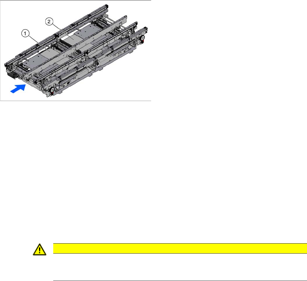
1. TSP410 lane 1 (under the cover)
2. TSP410 lane 2 (under the cover)
For an overview of the connectors, switches etc. of the
TSP410, refer to section "6.3.3 Conveyor control
TSP410" [ ➙ 291].
The single conveyor has one TSP410 fitted (PA1), the
dual and quad lane conveyors each have two.
CAUTION
Installation instructions
► Check the firmware and perform a download, if needed. (See "5.8.1 Firmware Download
(SW 70x)" [ ➙ 266])