SIPLACE-SX4-DX4-用户手册.pdf - 第140页
Service Work Placement heads 3.7.2 Replacing the C&P20/A/M Head 140 Service Manual SIPLACE SX4/DX4 Removal ► Switch off the machine, disconnec t it from the po wer supply and secure it to prev ent unauth orized react…

Service Work
3.7.2 Replacing the C&P20/A/M Head Placement heads
Service Manual SIPLACE SX4/DX4 139
3.7.2
3.7.2 Replacing the C&P20/A/M Head
Replacing the C&P20/A/M Head
Parts, equipment and tools
▪ Select the placement head:
▪ Torque screwdriver 100-500 Ncm [03078400-xx]
▪ Extension/straight TX20 [03073256-xx]
▪ Bit holder for Torque Vario-S screwdriver [03078706-xx]
▪ Torx Allen screwdriver TX8 [03080081-xx]
▪ Calibration tool version SST23 [03034148-xx]
▪ Protective hose for component sensor [03078596-xx]
▪ For additional work to the placement head:
Service manual "C&P20 / C&P20 A / C&P20 M head" [DE: 00197464-xx] [EN: 00197465-xx]
▪ For vacuum pump mode, if required:
- assembly instructions "Vacuum pump X-Series S, SX4/DX4" [00196845-xx]
- assembly instructions "Vacuum pump SX1/2, DX1/2" [00196614-xx]
- assembly instructions "Vacuum pump X-Series (SC 70x)" [00196433-xx]
- assembly instructions "Vacuum pump X-Series" [00195089-xx]
NOTICE
Fast Head Exchange (FHE)
► Observe the instructions in section "3.7.1 Fast Head Exchange" [➙134] when exchanging
a head.
NOTICE
Example
Replacement of the placement head is shown using the example of a C&P20 A machine. The
replacement procedure for other C&P20 placement heads is the same. Any differences will be
explicitly indicated.
Head type Item no.
C&P20 A 03062095-xx – with camera
03058420-xx – without camera
C&P20 M 03103108-xx – without camera
Service Work
Placement heads 3.7.2 Replacing the C&P20/A/M Head
140 Service Manual SIPLACE SX4/DX4
Removal
► Switch off the machine, disconnect it from the power supply and secure it to prevent unauthorized
reactivation. Observe the instructions in section "1.2 Preparatory Work..." [ ➙ 12].
► Loosen all four M4 fastening screws with a long Torx key.
► Carefully lift the head out of the locating pins on the head plate.
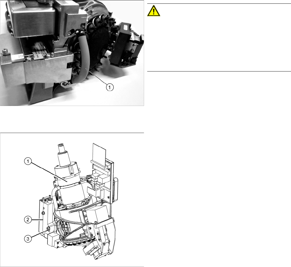
Hose on component sensor (example of C&P20 A
shown)
CAUTION!
The component sensor prisms, underneath the place-
ment head, are easily damaged. Take great care when
dismantling the head!
Protect the component sensor with a piece of hose (1).
This is delivered with the placement head or component
sensor and should be stored in the service box for the
machine, as it is required for dismantling the head.
► Disconnect the compressed air connection (1).
► Disconnect the flat ribbon cables from the C&P20A.
► Loosen the screws fastening the strain relief on the
component camera cables and carefully unplug the
cables. While unplugging the cables, press the
clamps on both sides of the connectors.
► Loosen the two screws on the pressure control valve
(2).
► Remove the screw (3) from the pressure control
valve and swing the pressure control valve to one
side.
The head fastening screw near the pressure control
valve is now accessible.

Service Work
3.7.2 Replacing the C&P20/A/M Head Placement heads
Service Manual SIPLACE SX4/DX4 141
Installation
► Follow the removal instructions in reverse order for installation. Also observe the following instruc-
tions:
See also
3.7.5 Installation Positions on the Head Plate [ ➙ 149]
3.7.3 Replacing the CPP Head [ ➙ 142]
3.7.4 Replacing the Twin/VHF Head [ ➙ 146]
3.7.5 Installation Positions on the Head Plate [ ➙ 149]
CAUTION
Installation instructions
► If you replace the head without the component camera, you will need to fit the old camera
into the new head. Read the service manual for your placement head for more information.
► In vacuum pump mode, you need to dismantle the silencer from the old head and fit it to the
new one. Refer to the appropriate vacuum pump assembly instructions for details.
► Make sure that the assembly position on the head plate is correct.
► Tighten the four head fastening screws (M4) with a torque of 2.7 Nm.