SIPLACE-SX4-DX4-用户手册.pdf - 第149页
Service Work 3.7.5 Installation Positions on the Head Plate Placement heads Service Manual SIPLACE SX4/DX4 149 3.7.5 3 . 7 . 5 I n s t a lla t io n P o s it io n s o n t h e H e a d P la t e Installation Position s on th…
Service Work
Placement heads 3.7.4 Replacing the Twin/VHF Head
148 Service Manual SIPLACE SX4/DX4
Installation
► Follow the removal instructions in reverse order for installation. Also observe the following instruc-
tions:
See also
5.8.2 Calibration [ ➙ 267]
5.8.2.1 Calibrating the Heads and Cameras [ ➙ 267]
3.7.2 Replacing the C&P20/A/M Head [ ➙ 139]
3.7.3 Replacing the CPP Head [ ➙ 142]
3.7.5 Installation Positions on the Head Plate [ ➙ 149]
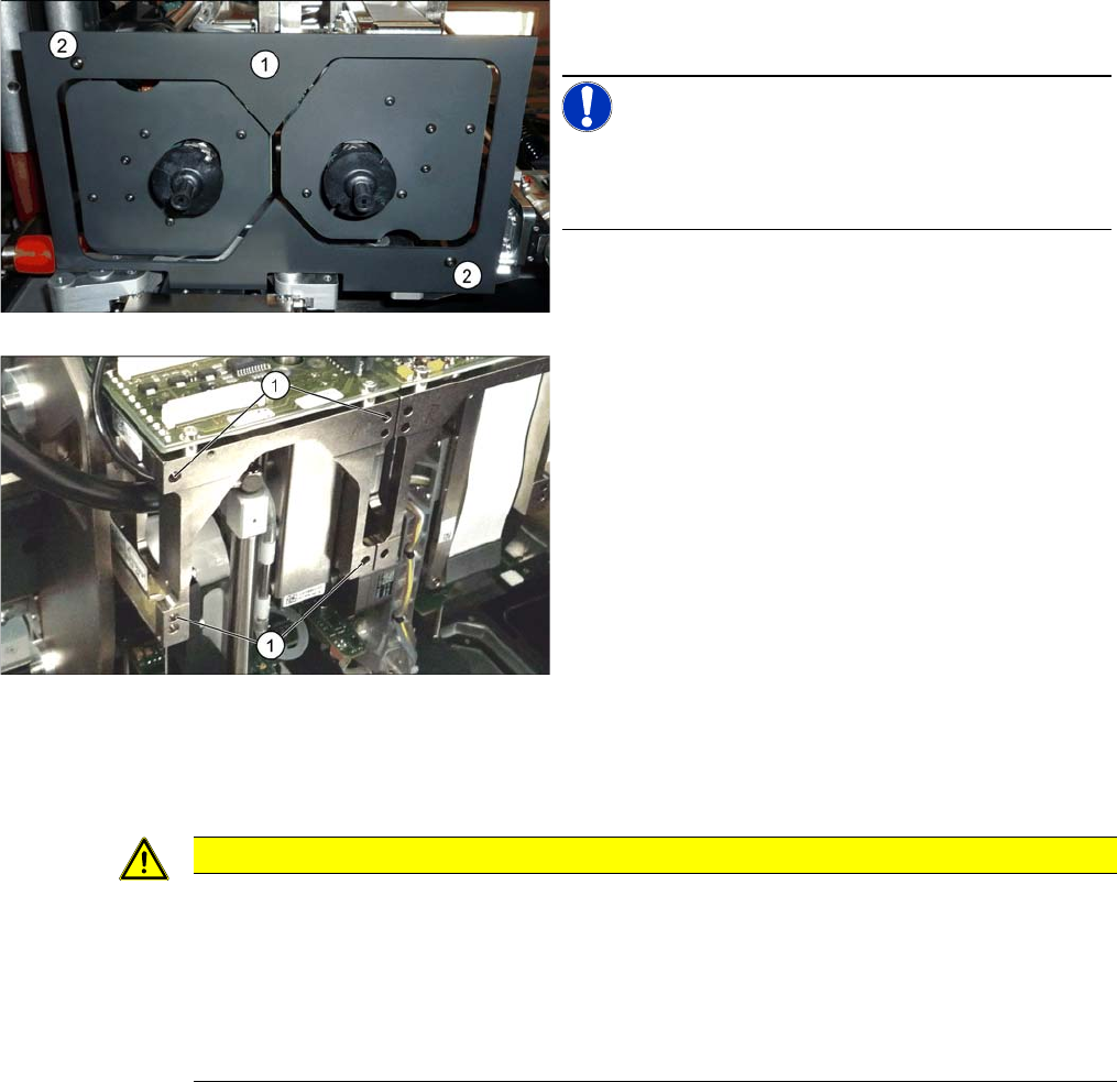
► Remove the camera screen (1). This is fastened with
two black screws (2).
NOTICE!
Only use these screws to fix the camera screen. This pre-
vents reflection when measuring components with the
stationary camera.
Each module is fixed with four screws to the head plate
and is positioned with two pins.
► Loosen the four M4x14 fastening screws (1) with a
long Allen key.
► Pull the module out of the locating pins.
CAUTION
Installation instructions
► Fit the fastening screws on the other side of the module, if needed (see above).
► Make a note of the force values for the new module. These force values can be found on a
label at the side of the module.
► Make sure that the assembly position is correct.
► Perform head calibration.
Service Work
3.7.5 Installation Positions on the Head Plate Placement heads
Service Manual SIPLACE SX4/DX4 149
3.7.5
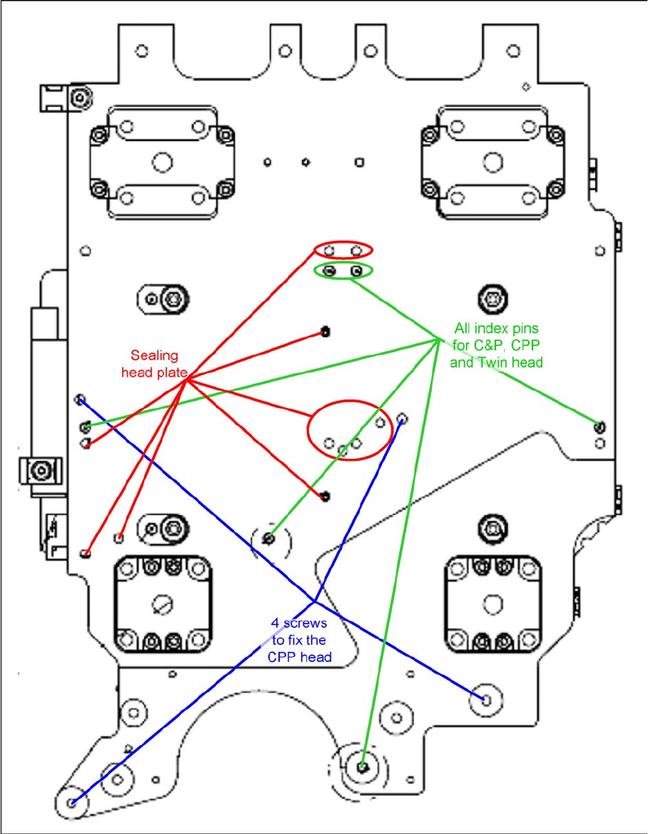
3.7.5 Installation Positions on the Head Plate
Installation Positions on the Head Plate

Service Work
Placement heads 3.7.6 Replacing Stationary Component Camera Digital Type 25/33/36
150 Service Manual SIPLACE SX4/DX4
3.7.6
3.7.6 Replacing Stationary Component Camera Digital Type 25/33/36
Replacing Stationary Component Camera Digital Type 25/33/36
Refer to the appropriate assembly instructions:
X series, SX series, D3 and D1:
▪ Assembly Instructions Stationary Camera 25 (FC) [00194554-xx] (German and English)
▪ Assembly Instructions Stationary Camera Type 33/36 (IC) [00196608-xx] (German and English)
X Series S:
▪ Assembly Instructions Stationary Camera type 25/33 [00197397-xx] (German and English)
See also
5.8.4 DIP Switch for Camera Types 25 and 33 [ ➙ 270]
CAUTION
Risk of injury with cameras of type 25
A heavy mark caul is mounted with the same fixture screws for cameras of type 25. This mark
caul is otherwise only held by the locating pins. If this mark caul falls down, it could cause inju-
ries.
► Make sure that this mark caul is not pulled off the locating pins.
NOTICE
Camera adaptor
You may need to fit an IC camera adaptor assembly. (See the assembly instructions)
► Location 1 to 3: IC camera adaptor assembly SX4a [03099054-xx]
► Location 4: IC camera adaptor assembly SP4 SX4a [03099004-xx]