SIPLACE-SX4-DX4-用户手册.pdf - 第152页
Service Work CPP/C&P20 Nozzle Changer 3.8.1 Replacing the Nozzle Change r 152 Service Manual SIPLACE SX4/DX4 3.8 3 . 8 C P P / C & P 2 0 N o z z le C h a n g e r CPP/C&P20 Nozzle Changer 3.8.1 3 . 8 . 1 R e p…
Service Work
3.7.6 Replacing Stationary Component Camera Digital Type 25/33/36 Placement heads
Service Manual SIPLACE SX4/DX4 151
3.7.6.1
3.7.6.1 Installation Height of the Stationary Camera
Installation Height of the Stationary Camera
The installation height at which the camera can be installed depends on the camera version. You will
either only be able to use one specific height or will have the option of several installation heights. The
following description only applies for the following camera versions with three possible installation
heights:
▪ Stationary component camera P&P (type 33) 55x45 digit. [03016339-xx] from version -06
▪ Stationary component camera P&P (type 36) 32x32 digit. [03042491-xx] from version -04
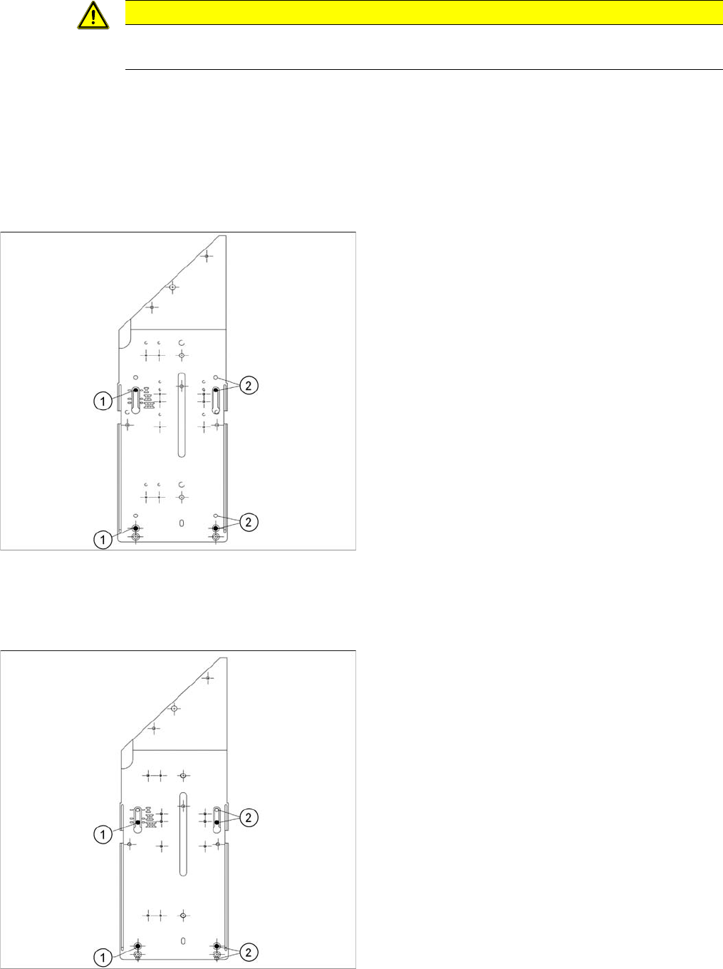
Stationary Camera in Position 1
Stationary Camera in Position 2
Position 2 is not relevant for the SX and the X series.
Stationary Camera in Position 3
CAUTION
Head crash danger
An incorrect installation height can result in a head crash!
1. Screw
2. Thread in the machine frame
Position 1 has to be used in the following cases:
▪ SX1/SX2: always
▪ SX4, X series: If at least one DLM or CPP head is
used in the corresponding placement area.
1. Screw
2. Thread in the machine frame
Position 3 has to be used in the following cases:
▪ SX1/SX2: never.
▪ SX4, X series: If only TwinHeads are used in the cor-
responding placement area.
Service Work
CPP/C&P20 Nozzle Changer 3.8.1 Replacing the Nozzle Changer
152 Service Manual SIPLACE SX4/DX4
3.8
3.8 CPP/C&P20 Nozzle Changer
CPP/C&P20 Nozzle Changer
3.8.1
3.8.1 Replacing the Nozzle Changer
Replacing the Nozzle Changer
Parts, equipment and tools
Select the relevant nozzle changers:
▪ NC basic structure CPx/all assembly long [03103514-xx] (replaces [03070123-xx])
▪ NC basic structure CPx/all assembly short [03103649-xx] (replaces [03062463-xx])
▪ Nozzle changer CPP X-Series [00119741-xx]
▪ Nozzle changer 2 CPP X-Series [00119742-xx]
▪ Nozzle changer C&P20 SX4/DX4 [00519851-xx]
▪ Nozzle changer CPP SX-Series (short) [00519841-xx]
▪ Nozzle changer CPP SX-Series (short, pos. 3 or 4) [00519842-xx]
▪ Nozzle changer C&P20 SX1/SX2 [00519715-xx]
▪ Nozzle changer C&P20 SX1/SX2 (pos. 3 or 4) [00519843-xx]
▪ If required, NC adjusting plates [03021079-xx]
▪ Depth measuring gauge (300 mm) [03079617-xx]
▪ Plastic plate
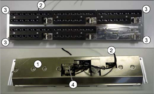
Overview
Removal/installation
► Switch off the machine, disconnect it from the power supply and secure it to prevent unauthorized
reactivation. Observe the instructions in section "1.2 Preparatory Work..." [ ➙ 12].
► Loosen the four fastening screws (4).
► Unplug the nozzles changer from all electrical and pneumatic connections.
► Take care not to lose the support plates. Remember their exact positions, as they will need to be
returned to these original positions, during assembly.
► Fit the new nozzle changer with the support plates.
► Reconnect to the electrical and compressed air systems.
► Check the mechanical height of the nozzle changer (see "5.6.1 Setting the Nozzle Changer Height"
[ ➙ 263]).
1. Cover (covering complete electronic and pneumatic
systems)
2. Compressed air connection
3. Four fastening screws
4. Valve
Service Work
3.8.2 Replacing the Complete Valve [03016830-xx] CPP/C&P20 Nozzle Changer
Service Manual SIPLACE SX4/DX4 153
3.8.2
3.8.2 Replacing the Complete Valve [03016830-xx]
Replacing the Complete Valve [03016830-xx]
Parts, equipment and tools
▪ Valve assembly [03016830-xx] (X series)
▪ Valve assembly CPx [03064012-xx] (X series with CPP, SX4, X series S)
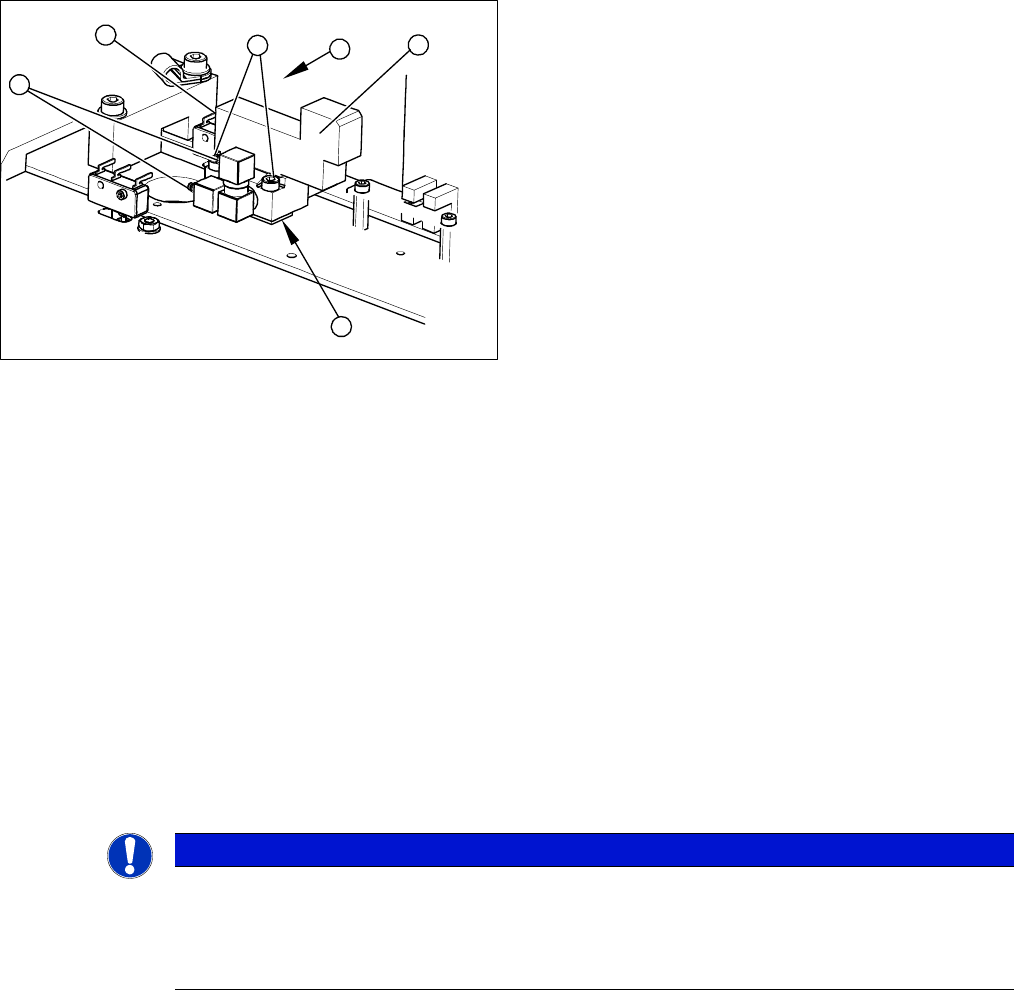
Overview
Removal
► Remove the nozzle changer from the machine. (See "3.8.1 Replacing the Nozzle Changer" [➙152])
► Loosen the six screws fastening the cover on the underside of the nozzle changer.
► Unplug the three compressed air connections (3) from the valve. Mark their positions, to make clear
assignment easier later on.
► Disconnect the board from the power supply (4).
► Loosen the two fastening screws (2).
► Remove the valve (1).
Take care not to lose the shim (5). This needs to be replaced in the correct position again, during
assembly.
Installation
► Installation is performed by following the above instructions in the reverse order. Also observe the
following instructions:
1. Valve assembly
2. Two fastening screws
3. Three pneumatic connections
4. Electrical connection
4
3
3
5
1
2
NOTICE
Installation instructions
► Remove the cable from the old valve and fit to the new one.
► Check the mechanical height of the nozzle changer (see "5.6.1 Setting the Nozzle Changer
Height" [ ➙ 263]).