SIPLACE-SX4-DX4-用户手册.pdf - 第153页
Service Work 3.8.2 Replacing the Complete Valve [03016830-xx] CPP/C&P20 Nozzl e Changer Service Manual SIPLACE SX4/DX4 153 3.8.2 3 . 8 . 2 R e p la c in g t h e C o m p le t e V a lv e [ 0 3 0 1 6 8 3 0 - x x ] Repla…
Service Work
CPP/C&P20 Nozzle Changer 3.8.1 Replacing the Nozzle Changer
152 Service Manual SIPLACE SX4/DX4
3.8
3.8 CPP/C&P20 Nozzle Changer
CPP/C&P20 Nozzle Changer
3.8.1
3.8.1 Replacing the Nozzle Changer
Replacing the Nozzle Changer
Parts, equipment and tools
Select the relevant nozzle changers:
▪ NC basic structure CPx/all assembly long [03103514-xx] (replaces [03070123-xx])
▪ NC basic structure CPx/all assembly short [03103649-xx] (replaces [03062463-xx])
▪ Nozzle changer CPP X-Series [00119741-xx]
▪ Nozzle changer 2 CPP X-Series [00119742-xx]
▪ Nozzle changer C&P20 SX4/DX4 [00519851-xx]
▪ Nozzle changer CPP SX-Series (short) [00519841-xx]
▪ Nozzle changer CPP SX-Series (short, pos. 3 or 4) [00519842-xx]
▪ Nozzle changer C&P20 SX1/SX2 [00519715-xx]
▪ Nozzle changer C&P20 SX1/SX2 (pos. 3 or 4) [00519843-xx]
▪ If required, NC adjusting plates [03021079-xx]
▪ Depth measuring gauge (300 mm) [03079617-xx]
▪ Plastic plate
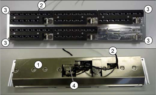
Overview
Removal/installation
► Switch off the machine, disconnect it from the power supply and secure it to prevent unauthorized
reactivation. Observe the instructions in section "1.2 Preparatory Work..." [ ➙ 12].
► Loosen the four fastening screws (4).
► Unplug the nozzles changer from all electrical and pneumatic connections.
► Take care not to lose the support plates. Remember their exact positions, as they will need to be
returned to these original positions, during assembly.
► Fit the new nozzle changer with the support plates.
► Reconnect to the electrical and compressed air systems.
► Check the mechanical height of the nozzle changer (see "5.6.1 Setting the Nozzle Changer Height"
[ ➙ 263]).
1. Cover (covering complete electronic and pneumatic
systems)
2. Compressed air connection
3. Four fastening screws
4. Valve
Service Work
3.8.2 Replacing the Complete Valve [03016830-xx] CPP/C&P20 Nozzle Changer
Service Manual SIPLACE SX4/DX4 153
3.8.2
3.8.2 Replacing the Complete Valve [03016830-xx]
Replacing the Complete Valve [03016830-xx]
Parts, equipment and tools
▪ Valve assembly [03016830-xx] (X series)
▪ Valve assembly CPx [03064012-xx] (X series with CPP, SX4, X series S)
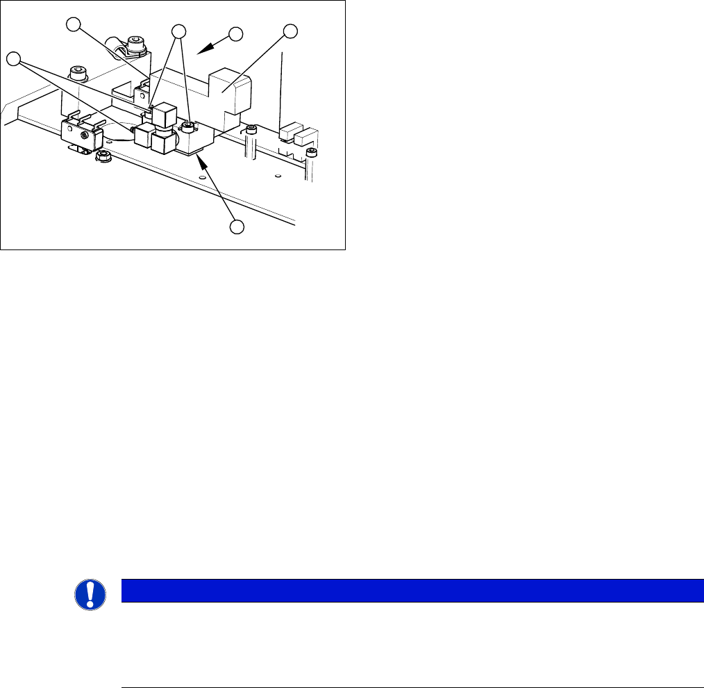
Overview
Removal
► Remove the nozzle changer from the machine. (See "3.8.1 Replacing the Nozzle Changer" [➙152])
► Loosen the six screws fastening the cover on the underside of the nozzle changer.
► Unplug the three compressed air connections (3) from the valve. Mark their positions, to make clear
assignment easier later on.
► Disconnect the board from the power supply (4).
► Loosen the two fastening screws (2).
► Remove the valve (1).
Take care not to lose the shim (5). This needs to be replaced in the correct position again, during
assembly.
Installation
► Installation is performed by following the above instructions in the reverse order. Also observe the
following instructions:
1. Valve assembly
2. Two fastening screws
3. Three pneumatic connections
4. Electrical connection
4
3
3
5
1
2
NOTICE
Installation instructions
► Remove the cable from the old valve and fit to the new one.
► Check the mechanical height of the nozzle changer (see "5.6.1 Setting the Nozzle Changer
Height" [ ➙ 263]).
Service Work
Cutter 3.9.1 Replacing the Cutter on the COT Insert [03066690-xx]
154 Service Manual SIPLACE SX4/DX4
3.9
3.9 Cutter
Cutter
3.9.1
3.9.1 Replacing the Cutter on the COT Insert [03066690-xx]
Replacing the Cutter on the COT Insert [03066690-xx]
Parts, equipment and tools
▪ Cutter, pneumatic SIPLACE HF/X series [03066690-xx]
▪ If needed, mounting plate [00312731-xx]
Alternatively: two large parallel clamps and a sturdy table with even surface to clamp down the dis-
mantled cutter
Removal
► Switch off the machine, disconnect it from the power supply and secure it to prevent unauthorized
reactivation. Observe the instructions in section "1.2 Preparatory Work..." [ ➙ 12].
Pneumatics Sy stem - Shutting off the Compressed Air Supply
NOTICE
COT insert
The cutter can be removed without dismantling the COT insert.
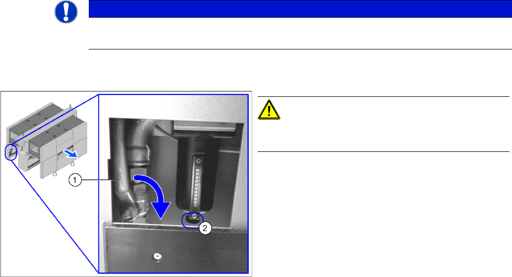
Disabling the compressed air supply
CAUTION!
When working on the pneumatic system, always switch
off the compressed air supply.
► Push the lever (1) for the compressed air supply
back, until it is positioned horizontally.
► Open the screw (2) on the inlet filter to vent the sys-
tem. Hold a cloth underneath to capture any escaping
oil.
► All manometers must be set to zero.