SIPLACE-SX4-DX4-用户手册.pdf - 第155页
Service Work 3.9.1 Replacing the Cutter on the COT Inser t [03066690-xx] Cutter Service Manual SIPLACE SX4/DX4 155 1. Cutter 2. Pneumatic cylinder 3. Waste tape conta iner ► Loosen the four screws fastening the waste tap…
Service Work
Cutter 3.9.1 Replacing the Cutter on the COT Insert [03066690-xx]
154 Service Manual SIPLACE SX4/DX4
3.9
3.9 Cutter
Cutter
3.9.1
3.9.1 Replacing the Cutter on the COT Insert [03066690-xx]
Replacing the Cutter on the COT Insert [03066690-xx]
Parts, equipment and tools
▪ Cutter, pneumatic SIPLACE HF/X series [03066690-xx]
▪ If needed, mounting plate [00312731-xx]
Alternatively: two large parallel clamps and a sturdy table with even surface to clamp down the dis-
mantled cutter
Removal
► Switch off the machine, disconnect it from the power supply and secure it to prevent unauthorized
reactivation. Observe the instructions in section "1.2 Preparatory Work..." [ ➙ 12].
Pneumatics Sy stem - Shutting off the Compressed Air Supply
NOTICE
COT insert
The cutter can be removed without dismantling the COT insert.
Disabling the compressed air supply
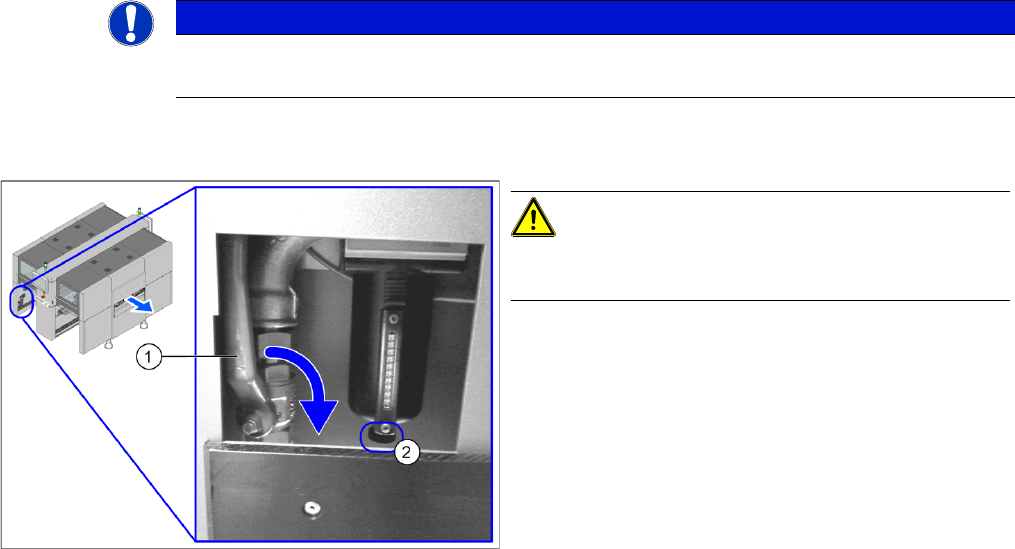
CAUTION!
When working on the pneumatic system, always switch
off the compressed air supply.
► Push the lever (1) for the compressed air supply
back, until it is positioned horizontally.
► Open the screw (2) on the inlet filter to vent the sys-
tem. Hold a cloth underneath to capture any escaping
oil.
► All manometers must be set to zero.
Service Work
3.9.1 Replacing the Cutter on the COT Insert [03066690-xx] Cutter
Service Manual SIPLACE SX4/DX4 155
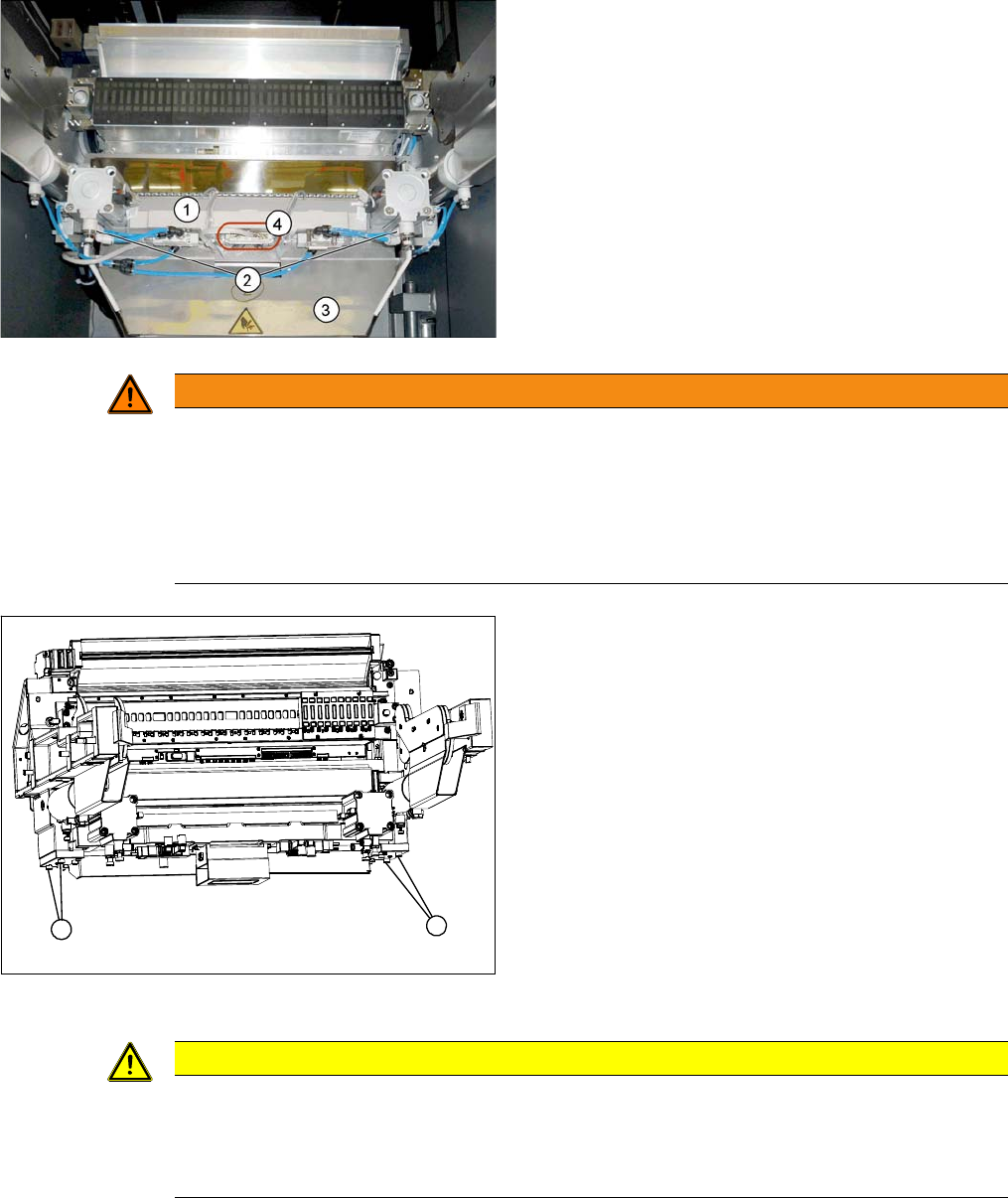
1. Cutter
2. Pneumatic cylinder
3. Waste tape container
► Loosen the four screws fastening the waste tape con-
tainer (3) and remove this container.
► Loosen the compressed air connections for the short-
stroke cylinder (2) at the coupling.
► Unplug the electrical connections (4) to the cutter by
pressing the connector at the side and pulling it off.
WARNING
Risk of injury when releasing the fixtures!
The cutter is only held by the fastening screws and is not supported by other parts. If the four
fastening screws are loosened, the cutter will fall down and out of the machine.
► Make sure that no one is under the cutter!
► Support the cutter by placing a suitable object (e.g. height-adjustable support or chair) un-
der it.
COT insert (using example of X series)
► Loosen the four fastening screws (1) on the cutter
mount.
► Carefully lower the cutter and lift it out of the machine.
1
1
CAUTION
Additional work
► For all further work, either fix the cutter to the mounting plate with four hexagon socket-head
screws (M6) or use screw clamps to fasten the cutter to a sturdy table.
► Do not place the cutter onto the pneumatic connections down on the lifting cylinders.
Service Work
Cutter 3.9.1 Replacing the Cutter on the COT Insert [03066690-xx]
156 Service Manual SIPLACE SX4/DX4
Installation
► Move the cutter into its installation position, using the support/chair for assistance.
► Carefully lift the cutter into the planned position.
► Tighten all four fastening screws.
► Reconnect to the electrical and compressed air systems.
► Fit the waste tape container.
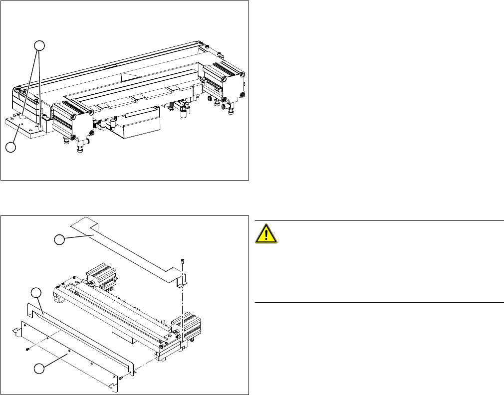
Cutter (using example of X series)
► Remove the two fixtures (1) on the left and right and
attach these with the spacer sleeves (2) to the new
cutter.
⇨ There may also be other shims in-between, which
will then need to be fitted back in the correct posi-
tion after service work.
► Carefully lift the cutter onto the spacer sleeves. Use
the spacer disks if provided.
► Tighten all four fastening screws.
Cutter (using example of X series)
CAUTION!
There is a risk of injuring yourself on the cutting edge of
the blades.
For this reason, the deflector plate (2), cover (1) and pro-
tective sheet (3) must be left mounted in place.
2
1
1
3
2