SIPLACE-SX4-DX4-用户手册.pdf - 第157页
Service Work 3.9.2 Replacing the Baffle Plate [03019896-xx] Cutter Service Manual SIPLACE SX4/DX4 157 3.9.2 3 . 9 . 2 R e p la c in g t h e B a f f le P la t e [ 0 3 0 1 9 8 9 6 - x x ] Replacing the Baffle Plate [030198…
Service Work
Cutter 3.9.1 Replacing the Cutter on the COT Insert [03066690-xx]
156 Service Manual SIPLACE SX4/DX4
Installation
► Move the cutter into its installation position, using the support/chair for assistance.
► Carefully lift the cutter into the planned position.
► Tighten all four fastening screws.
► Reconnect to the electrical and compressed air systems.
► Fit the waste tape container.
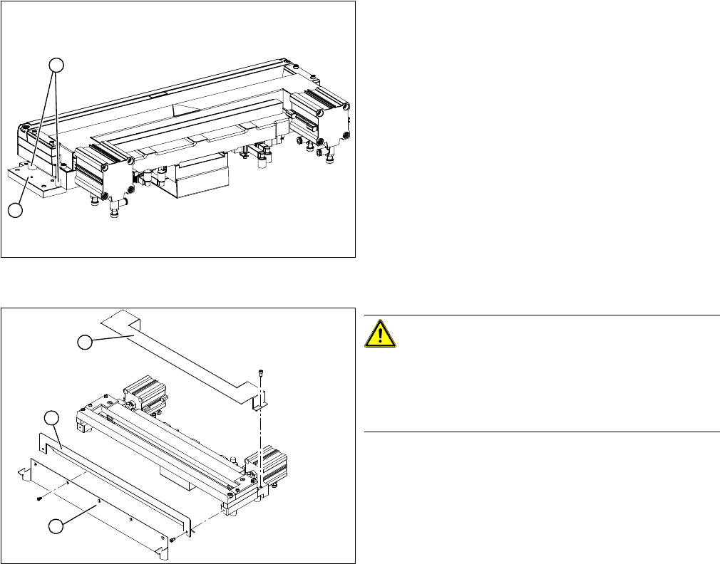
Cutter (using example of X series)
► Remove the two fixtures (1) on the left and right and
attach these with the spacer sleeves (2) to the new
cutter.
⇨ There may also be other shims in-between, which
will then need to be fitted back in the correct posi-
tion after service work.
► Carefully lift the cutter onto the spacer sleeves. Use
the spacer disks if provided.
► Tighten all four fastening screws.
Cutter (using example of X series)
CAUTION!
There is a risk of injuring yourself on the cutting edge of
the blades.
For this reason, the deflector plate (2), cover (1) and pro-
tective sheet (3) must be left mounted in place.
2
1
1
3
2
Service Work
3.9.2 Replacing the Baffle Plate [03019896-xx] Cutter
Service Manual SIPLACE SX4/DX4 157
3.9.2
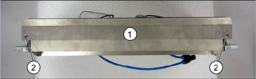
3.9.2 Replacing the Baffle Plate [03019896-xx]
Replacing the Baffle Plate [03019896-xx]
Parts, equipment and tools
▪ Baffle plate (SIPLACE HF) [03019896-xx]
Removal
Installation
► Follow the removal instructions in reverse order for installation.
See also
1.2 Preparatory Work... [ ➙ 12]
► Remove the cutter from the machine. (See "3.9.1 Re-
placing the Cutter on the COT Insert [03066690-xx]"
[ ➙ 154])
The baffle plate (1) is located on the back of the cutter.
► Loosen the two screws (2) fastening the baffle plate
and then remove the baffle plate.
Service Work
Cutter 3.9.3 Replacing the Articulated Joint on the Short-Stroke Cylinder [03000518-xx]
158 Service Manual SIPLACE SX4/DX4
3.9.3
3.9.3 Replacing the Articulated Joint on the Short-Stroke Cylinder [03000518-xx]
Replacing the Articulated Joint on the Short-Stroke Cylinder [03000518-xx]
Parts, equipment and tools
▪ Articulated joint on the short-stroke cylinder [03000518-xx]
▪ 2x ISO4762-M5x35-12.9, geomet. 321+VL [03057290-xx] (screws for movable blade)
▪ Torque wrench 2.5 - 25 Nm [00376625-xx]
▪ Loctite 241 [02101037-xx]
▪ Klüber BEM 34-132 lubricant grease, 1 kg tin [00374565-xx]
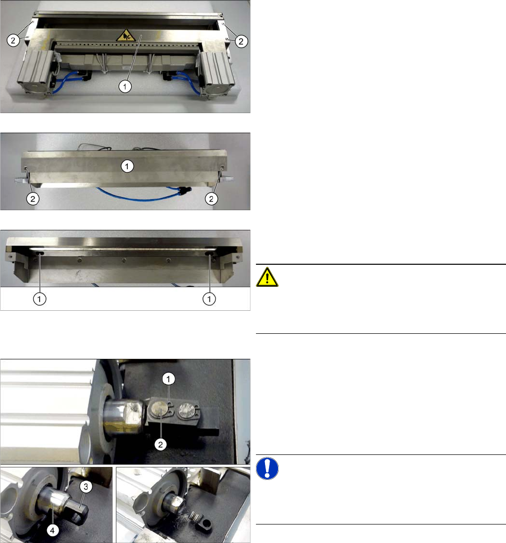
Removing the articulated joint
► Remove the cutter from the machine (see "3.9.1 Re-
placing the Cutter on the COT Insert [03066690-xx]"
[ ➙ 154]).
► Loosen the screws (2) fastening the top cover
plate (3) and then remove the cover plate.
► Loosen the screws (2) fastening the baffle plate (3) to
the back of the cutter and remove the baffle plate.
► Remove the caps over the fastening screws (1) on
the movable blade and loosen the blade.
CAUTION!
Risk of injury!
There is a risk of injuring yourself on the cutting edge of
the blades.
► Loosen the circlip (1).
► Push the piston rod a little into the short-stroke cylin-
der and rotate the articulated joint by 90 degrees.
► Push the bolt (2) out of the articulated joint.
► Unscrew the remaining articulated joint adapter (3)
from the piston (4).
NOTICE!
The adapter is secured with locking varnish (Loctite no.
241). You will need somewhat more strength than usual
to loosen it.