SIPLACE-SX4-DX4-用户手册.pdf - 第177页
Service Work 3.10.6 Replacing the Empty-T ape Duct Assembly [03052576-xx] COT insert Service Manual SIPLACE SX4/DX4 177 3.10.6 3 . 1 0 . 6 R e p la c in g t h e E m p t y - T a p e D u c t A s s e m b ly [ 0 3 0 5 2 5 7 …
Service Work
COT insert 3.10.5 Replacing the Safety Switch [03019065-xx]
176 Service Manual SIPLACE SX4/DX4
3.10.5
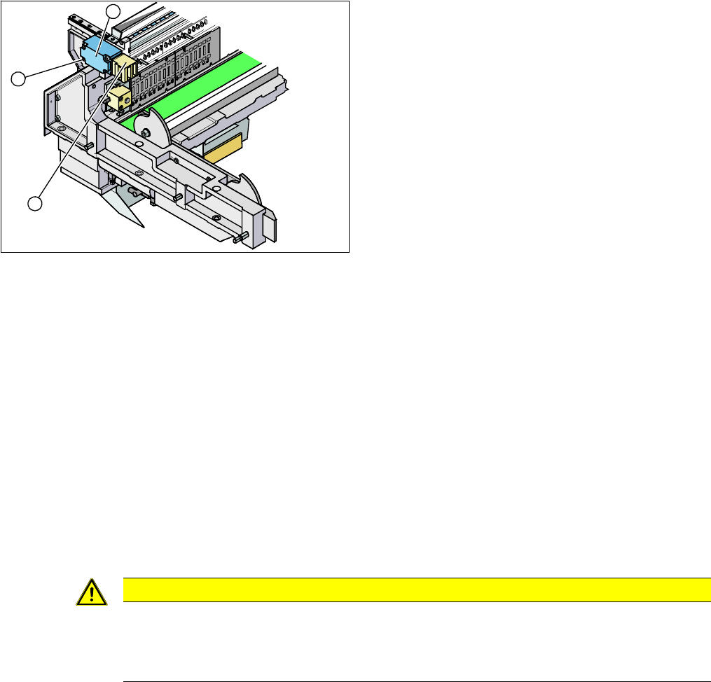
3.10.5 Replacing the Safety Switch [03019065-xx]
Replacing the Safety Switch [03019065-xx]
Parts, equipment and tools
▪ Safety switch [03019065-xx]
Overview
Removal
► Switch off the machine, disconnect it from the power supply and secure it to prevent unauthorized
reactivation. Observe the instructions in section "1.2 Preparatory Work..." [ ➙ 12].
► Depending on the options installed, you may need to loosen the COT insert and pull it slightly for-
wards for better access. For more information about this, read section Replacing the COT Insert As-
sembly.
► Dismantle the nozzle changer for better access.
► Loosen the screws fastening the safety switch.
► Unthread the connection cable up to the connectors down in the machine frame and to the feed con-
trol and then unplug it. Dismantle the two cover plates at the back of the COT insert.
Installation
► Installation is performed by following the above instructions in the reverse order. Also observe the
following instructions:
See also
5.1.1 Setting the Machine Covers [ ➙ 227]
1. Security switch
2. Four fastening screws
3. Contact jack
3
2
1
CAUTION
Installation instructions
► Move the component trolley into the COT insert and check whether the component trolley
can be moved into the contact jack. Correct the position of the safety switch, where neces-
sary.
Service Work
3.10.6 Replacing the Empty-Tape Duct Assembly [03052576-xx] COT insert
Service Manual SIPLACE SX4/DX4 177
3.10.6
3.10.6 Replacing the Empty-Tape Duct Assembly [03052576-xx]
Replacing the Empty-Tape Duct Assembly [03052576-xx]
Parts, equipment and tools
▪ COT insert:
SX4, DX4, X2 S, X3 S, X3 S, X4 S: empty tape duct assembly [03052576-xx]
X4i S: replacing the LLK ASP speed flex assembly [03089515-xx]
▪ Manual table:
X-Series S location 2: empty tape duct assembly M2 [03103926-xx]
X-Series S location 3: empty tape duct assembly M3 [03104547-xx]
Overview
Removal
► Switch off the machine, disconnect it from the power supply and secure it to prevent unauthorized
reactivation. Observe the instructions in section "1.2 Preparatory Work..." [ ➙ 12].
► Mark the position of the sensors (reed contacts) and remove these from the reject container.
► Remove the nozzle changer, if required.
► Dismantle the feeder unlocking device 40/2-fold. (See "3.10.3 Replacing the 40-Fold Feeder Unlock
Device [03011582-xx]" [ ➙ 173])
► Remove the FCU. (See "3.10.2 Replacing the Feeder Control Unit (FCU) [03059623-xx]" [ ➙ 172])
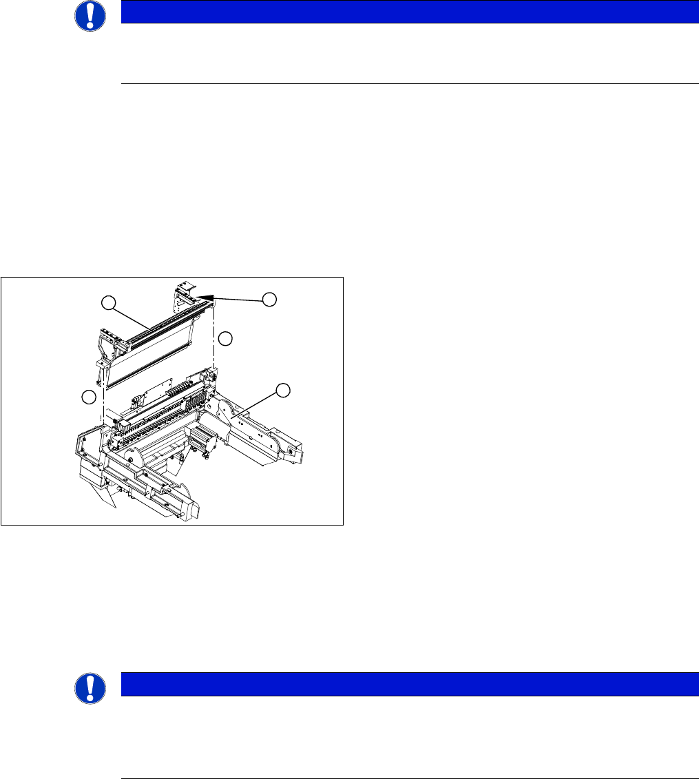
► Loosen the two screws (4) holding the empty-tape duct assembly (2). Depending on the version of
your COT insert, you may need to first dismantle the safety switch and the insert control, otherwise
the screws will not be accessible.
NOTICE
Manual and changeover table
The work described in this chapter applies both to the manual table and the changeover table.
Any relevant differences will be mentioned explicitly.
1. COT insert assembly
2. Empty-tape duct assembly
3. Position of the sensors
4
1
4
3
2
NOTICE
Manual table
If you are working on a manual table, you will need to also perform the following tasks before
dismantling the feeder unlocking device and the FCU.
► Dismantle the back and front section of the manual table.

Service Work
COT insert 3.10.6 Replacing the Empty-Tape Duct Assembly [03052576-xx]
178 Service Manual SIPLACE SX4/DX4
► Carefully lift the empty-tape duct (2) out of the COT insert (1).
Installation
Follow the removal instructions in reverse order for installation. Also observe the following instructions:
► Fit the sensors (reed contacts) for the reject container.
► Fit the empty-tape duct.
► When fitting the nozzle changer, observe the applicable assembly instructions, as you need to check
the installation height.
See also
3.8.1 Replacing the Nozzle Changer [ ➙ 152]
3.13.2 Removing the Back Section of the Manual Table [ ➙ 201]
3.13.3 Removing the Front Section of the Manual Table [ ➙ 202]
3.13.2 Removing the Back Section of the Manual Table [ ➙ 201]
3.13.3 Removing the Front Section of the Manual Table [ ➙ 202]
NOTICE
Unplug the cable from the FCU.
► You could also unplug the cable at the FCU. This gives you greater freedom of movement.
In this case, note the positions, to make clear assignment easier later on.
CAUTION
Risk of cutting
The cutter is located under the tape channel. The blades there have very sharp edges.
► Do not reach into the cutter and make sure that it is never left unmonitored or freely acces-
sible.
NOTICE
These sensors are installed in different positions, according to the configuration of the machine.
► Refer to the appropriate assembly instructions: