SIPLACE-SX4-DX4-用户手册.pdf - 第189页
Service Work 3.11.6 Replacing the Actuator/Protective Bracket X-Series Compon ent Trolley Service Manual SIPLACE SX4/DX4 189 3.11.6 3 . 1 1 . 6 R e p la c in g t h e A c t u a t o r / P r o t e c t iv e B r a c k e t Rep…
Service Work
X-Series Component Trolley 3.11.5 Replacing the Insert Feeder [03002898-xx]
188 Service Manual SIPLACE SX4/DX4
3.11.5
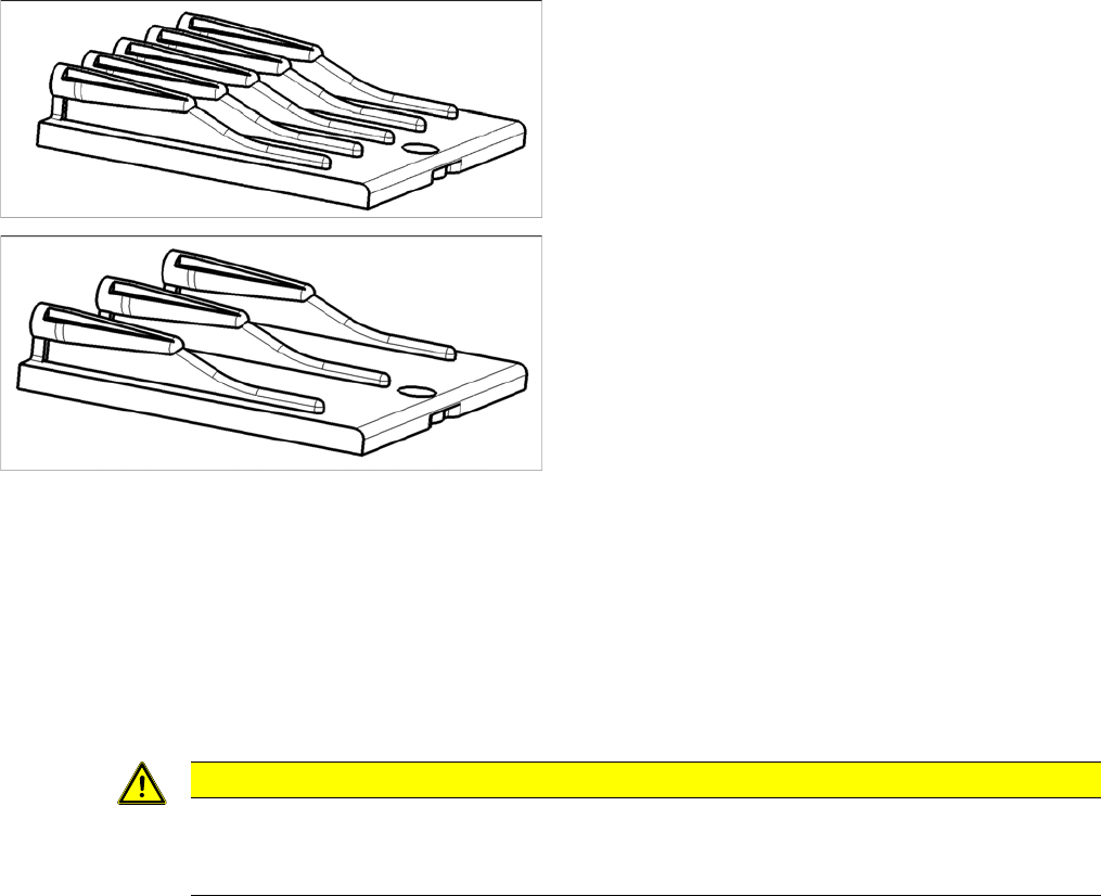
3.11.5 Replacing the Insert Feeder [03002898-xx]
Replacing the Insert Feeder [03002898-xx]
Parts, equipment and tools
Select the right insert feeder:
Removal
► Move the component trolley out of the machine.
► Loosen the screw fastening the guide profile and remove the guide profile.
Installation
► Follow the removal instructions in reverse order for installation. Also observe the following instruc-
tions:
Insert feeder [03002898-xx]
Suitable for:
▪ X-Series component trolley
▪ Component trolley SX1/SX2 (30 or 60 tracks)
▪ Manual table X-Series S
Insert feeder [03085635-xx]
Suitable for:
▪ Manual table DX series
CAUTION
Installation instructions
► Make sure that the insert is aligned properly with the guidance behind it. You must be able
to push feeder modules into the feeder location without edge interference.
Service Work
3.11.6 Replacing the Actuator/Protective Bracket X-Series Component Trolley
Service Manual SIPLACE SX4/DX4 189
3.11.6
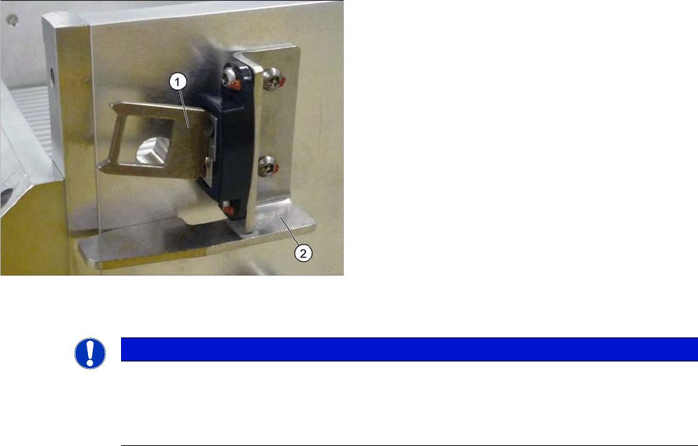
3.11.6 Replacing the Actuator/Protective Bracket
Replacing the Actuator/Protective Bracket
Parts, equipment and tools
▪ Torque wrench T20 with drilled hole (for screw ISO 7380-TX with pin - M4)
▪ Actuator AZ335 Schmersal [03013488-xx]
▪ Protective bracket: holder and protection for actuator [03095447-xx]
Overview
Installation
1. Actuator
2. Protective bracket
NOTICE
Installation instructions
► Tighten the fastening screws for the actuator on the protective bracket with amaximum
torque of 200 Ncm.
► Set the actuator (see "5.7.1 Setting the Actuator on the Component Trolley" [ ➙ 265]).
Service Work
Docking Station for X-Series Component Trolley 3.12.1 Replacing the Power Pack [03025938-XX]
190 Service Manual SIPLACE SX4/DX4
3.12
3.12 Docking Station for X-Series Component Trolley
Docking Station for X-Series Component Trolley
3.12.1
3.12.1 Replacing the Power Pack [03025938-XX]
Replacing the Power Pack [03025938-XX]
Parts, equipment and tools
▪ Circuit diagram folder for your machine
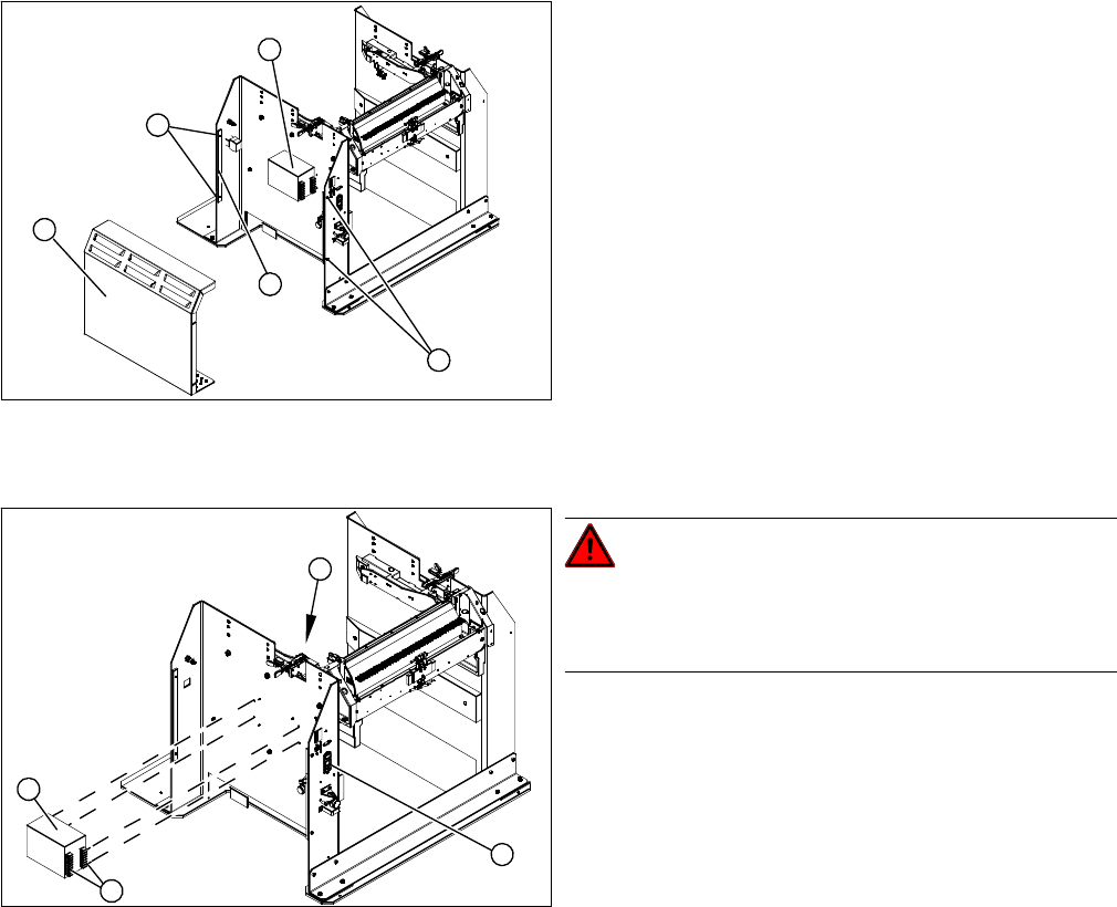
Overview
Removal/installation
► Reconnect the connection leads and install the new power pack.
► Connect the power pack connection cable and press the ON/OFF button to switch on.
► Set the output voltage of the power pack to 26.8 V (+/- 0.5 V) at terminals nine and twelve.
► Refit the cover.
1. Cover
2. Bar for clamping the cover
3. Fastening screws
4. Power pack
► Loosen the four screws (3) fastening the cover (1).
The cover is clamped in place with the help of the bar
(2).
► Pull the cover out of the docking station.
► Take care not to damage the earth connection.
4
3
1
3
2
DANGER!
Switch off the voltage supply
Press the ON/OFF button (1) to switch off, and discon-
nect the power supply.
► Loosen the four screws (2) fastening the power pack
(3) on the inside of the docking station.
► Label the connection leads and disconnect these
from the terminal strip (4).
4
3
1
2