SIPLACE-SX4-DX4-用户手册.pdf - 第205页
Service Work 3.13.5 Replacing the Feeder Lock on the Manual T able [03082778-xx] Manual Table (DX4) Service Manual SIPLACE SX4/DX4 205 Removal ► Further removal and installation of the feeder lock is the s ame as that fo…
Service Work
Manual Table (DX4) 3.13.4 Replacing the Locking Latch [03069205-xx]
204 Service Manual SIPLACE SX4/DX4
3.13.4
3.13.4 Replacing the Locking Latch [03069205-xx]
Replacing the Locking Latch [03069205-xx]
Parts, equipment and tools
▪ Single locking latch [03069205-xx]
▪ Tension spring [03010352-xx]
▪ Cover plate for locking strip [03077142-xx]
Removal/installation
► Dismantle the front and back sections.
► The procedure is the same for the component trolley. Please refer the instructions in section "3.11.2
Replacing the Locking Latch [03069205-xx]" [ ➙ 184].
See also
3.13.6.1 Operating the Unlocking Hook [ ➙ 208]
3.13.5 Replacing the Feeder Lock on the Manual Table [03082778-xx] [ ➙ 204]
3.13.5
3.13.5 Replacing the Feeder Lock on the Manual Table [03082778-xx]
Replacing the Feeder Lock on the Manual Table [03082778-xx]
Please also observe section "3.11.2 Replacing the Locking Latch [03069205-xx]" [ ➙ 184].
Parts, equipment and tools
Select the correct spare part:
▪ Rubber mallet
Overview
Machine type Designation Item No.
X-Series S Feeder lock/X-Series (1x) 03023777-xx
SX1/SX2, DX1/DX2 Feeder lock 30/2-fold
(1x per 30 track manual table or component trolley)
(2x per 60 track manual table or component trolley)
03081586-xx
DX4 Feeder lock 40-fold
(1x per manual table or component trolley)
03082778-xx
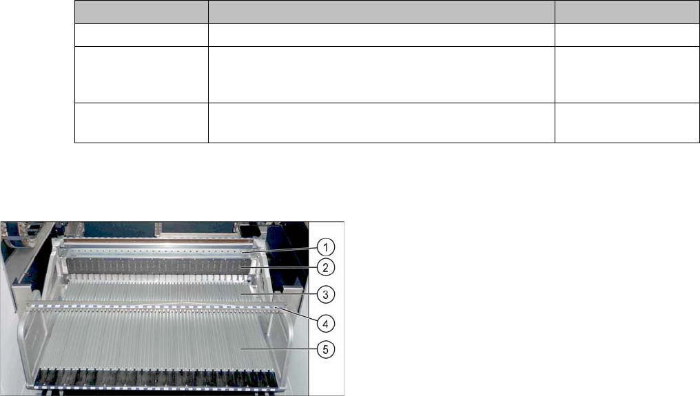
Manual table (using example of DX1/DX2)
1. Centering bar
2. FCU
3. Front section with feeder lock (with locking latches)
4. Fixture bar
5. Back part
Service Work
3.13.5 Replacing the Feeder Lock on the Manual Table [03082778-xx] Manual Table (DX4)
Service Manual SIPLACE SX4/DX4 205
Removal
► Further removal and installation of the feeder lock is the same as that for the front section of the man-
ual table. For more information about this, read section "3.13.3 Removing the Front Section of the
Manual Table" [ ➙ 202].
Installation
► Follow the removal instructions in reverse order for installation.
See also
3.13.2 Removing the Back Section of the Manual Table [ ➙ 201]
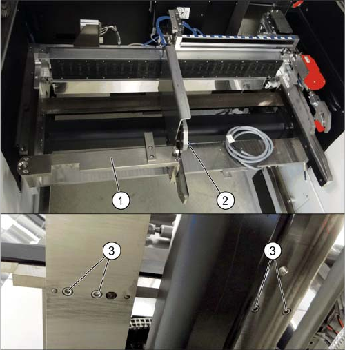
If there is a WPC at the same location, perform the follow-
ing two steps as well:
► Dismantle the WPC docking rail (1).
► Dismantle the left side of the insert mechanism (2).
Loosen the 4 fastening screws (3) on the underside
and the 2 fastening screws on the top of the empty
tape duct.
Service Work
Manual Table (DX4) 3.13.6 Replacing the Feeder Control Unit (FCU)
206 Service Manual SIPLACE SX4/DX4
3.13.6
3.13.6 Replacing the Feeder Control Unit (FCU)
Replacing the Feeder Control Unit (FCU)
Parts, equipment and tools
Select the correct spare part:
▪ Rubber mallet
Overview
NOTICE
Only every second location can be occupied.
We recommend that you use 2x8 mm feeders.
If you are using single 8 mm feeders, the location next to the feeder will be left empty.
NOTICE
Remove the feeder
Also observe section "3.13.6.1 Operating the Unlocking Hook" [ ➙ 208].
Machine type Designation Item No.
DX4 FCU 03082687-xx
DX1/DX2 FCU 03082605-xx
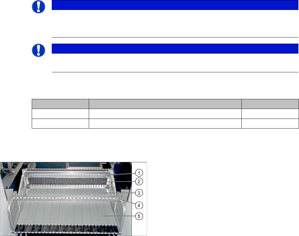
Manual table (using example of DX1/DX2)
1. Centering bar
2. FCU
3. Front part
4. Fixture bar
5. Back part