SIPLACE-SX4-DX4-用户手册.pdf - 第206页
Service Work Manual Table (DX4) 3.13.6 Replacing the Feeder Control U nit (FCU) 206 Service Manual SIPLACE SX4/DX4 3.13.6 3 . 1 3 . 6 R e p la c in g t h e F e e d e r C o n t r o l U n it ( F C U ) Replacing the Feeder …
Service Work
3.13.5 Replacing the Feeder Lock on the Manual Table [03082778-xx] Manual Table (DX4)
Service Manual SIPLACE SX4/DX4 205
Removal
► Further removal and installation of the feeder lock is the same as that for the front section of the man-
ual table. For more information about this, read section "3.13.3 Removing the Front Section of the
Manual Table" [ ➙ 202].
Installation
► Follow the removal instructions in reverse order for installation.
See also
3.13.2 Removing the Back Section of the Manual Table [ ➙ 201]
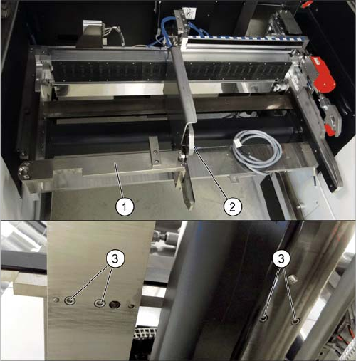
If there is a WPC at the same location, perform the follow-
ing two steps as well:
► Dismantle the WPC docking rail (1).
► Dismantle the left side of the insert mechanism (2).
Loosen the 4 fastening screws (3) on the underside
and the 2 fastening screws on the top of the empty
tape duct.
Service Work
Manual Table (DX4) 3.13.6 Replacing the Feeder Control Unit (FCU)
206 Service Manual SIPLACE SX4/DX4
3.13.6
3.13.6 Replacing the Feeder Control Unit (FCU)
Replacing the Feeder Control Unit (FCU)
Parts, equipment and tools
Select the correct spare part:
▪ Rubber mallet
Overview
NOTICE
Only every second location can be occupied.
We recommend that you use 2x8 mm feeders.
If you are using single 8 mm feeders, the location next to the feeder will be left empty.
NOTICE
Remove the feeder
Also observe section "3.13.6.1 Operating the Unlocking Hook" [ ➙ 208].
Machine type Designation Item No.
DX4 FCU 03082687-xx
DX1/DX2 FCU 03082605-xx
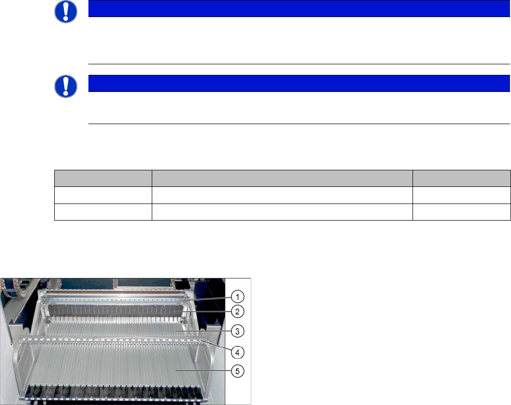
Manual table (using example of DX1/DX2)
1. Centering bar
2. FCU
3. Front part
4. Fixture bar
5. Back part

Service Work
3.13.6 Replacing the Feeder Control Unit (FCU) Manual Table (DX4)
Service Manual SIPLACE SX4/DX4 207
Removal
► Dismantle the back section of the manual table (see "3.13.2 Removing the Back Section of the Man-
ual Table" [ ➙ 201]).
► Dismantle the front section of the manual table (see "3.13.3 Removing the Front Section of the Man-
ual Table" [ ➙ 202]).
► Dismantle the feeder unlocking device and the FCU (see section "COT insert").
Installation
► Follow the removal instructions in reverse order for installation.
See also
3.10 COT insert [ ➙ 170]
3.10.3 Replacing the 40-Fold Feeder Unlock Device [03011582-xx] [ ➙ 173]
3.10.2 Replacing the Feeder Control Unit (FCU) [03059623-xx] [ ➙ 172]
If there is a WPC at the same location, perform the follow-
ing two steps as well:
► Dismantle the WPC docking rail (1).
► Dismantle the left side of the insert mechanism (2).
Loosen the 4 fastening screws (3) on the underside
and the 2 fastening screws on the top of the empty
tape duct.