SIPLACE-SX4-DX4-用户手册.pdf - 第226页
Measuring Equipmen t and Tools Component Sensor Protective Cap (CPP) [03080984-xx] 226 Service Manual SIPLACE SX4/DX4 4.20 4 . 2 0 C o m p o n e n t S e n s o r P r o t e c t iv e C a p ( C P P ) [ 0 3 0 8 0 9 8 4 - x x …
Measuring Equipment and Tools
Service Box SIPLACE SX [03079042-xx]
Service Manual SIPLACE SX4/DX4 225
4.17
4.17 Service Box SIPLACE SX [03079042-xx]
Service Box SIPLACE SX [03079042-xx]
The SIPLACE SX service box [03079042-xx] contains the following items:
▪ Filter element 430 [03003717-xx]
▪ 20x SIPLACE cleansing tissue [00315253-xx]
▪ Grease gun with tube and nozzle 230 [00374563Sxx]
▪ Klüber BEM 34-132 lubricant grease, 1 kg tin [00374565-xx]
▪ Filter insert 5 micrometer for series 112 [00355386-xx]
▪ Key close handle [03038882-xx]
4.18
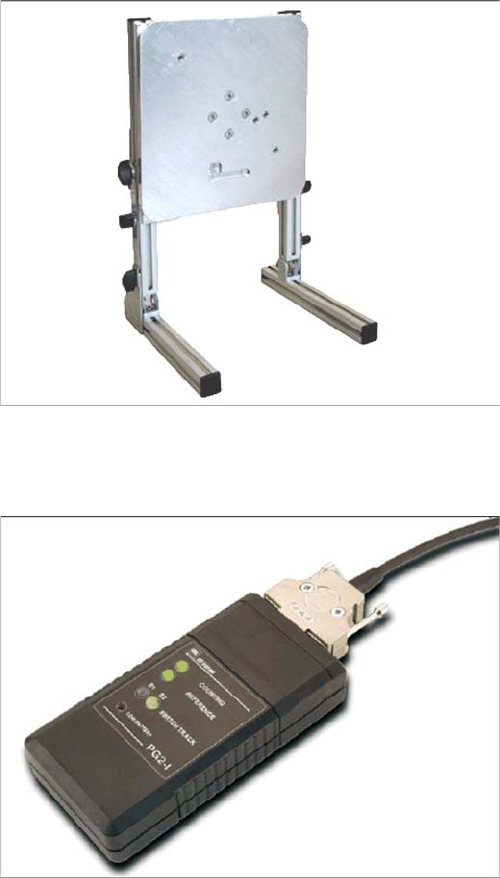
4.18 Universal Placement Head Mounting Rack [03056231-xx]
Universal Placement Head Mounting Rack [03056231-xx]
4.19
4.19 Read Head Test Device (Track Signal Tester) [03071361-xx]
Read Head Test Device (Track Signal Tester) [03071361-xx]
The universal placement head mounting rack is suitable
for TwinHead, C&P20, CPP, IC and DLM heads.
Read head test device [03071361-xx]
Measuring Equipment and Tools
Component Sensor Protective Cap (CPP) [03080984-xx]
226 Service Manual SIPLACE SX4/DX4
4.20
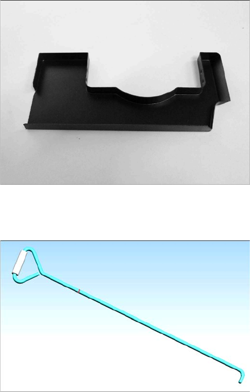
4.20 Component Sensor Protective Cap (CPP) [03080984-xx]
Component Sensor Protective Cap (CPP) [03080984-xx]
4.21
4.21 Unlocking Hook for Manual Table [03038882-xx]
Unlocking Hook for Manual Table [03038882-xx]
Component sensor protective cap for the CPP head
[03080984-xx]
In the event of an error (FCU failure,), the X feeders can
only be removed from the manual tables of the DX1/2 and
DX4 machines by using this unlocking hook.
Settings
5.1.1 Setting the Machine Covers Settings on the Basic Machine
Service Manual SIPLACE SX4/DX4 227
5
5 Settings
Settings
5.1
5.1 Settings on the Basic Machine
Settings on the Basic Machine
5.1.1
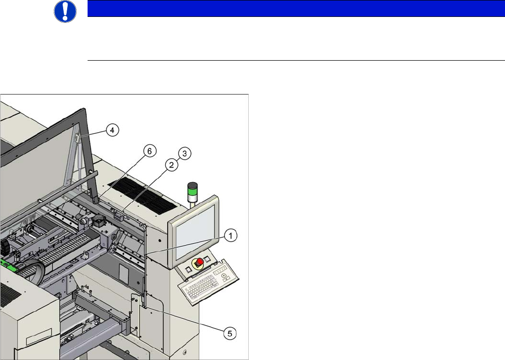
5.1.1 Setting the Machine Covers
Setting the Machine Covers
Overview
NOTICE
Example
The following settings are shown using the example of an SX2 machine. The procedure is the
same for other machines. Any differences will be explicitly indicated.
Settings (example of SX2 shown)
1. Setting the cover guidance
See "5.1.1.1 Setting the Cover Guidance" [ ➙ 228]
2. Setting the cover switch
See "5.1.1.2 Setting the Cover Switch" [ ➙ 229]
3. Setting the cover switch centering
See "5.1.1.3 Setting the Cover Switch Centering De-
vice" [ ➙ 230]
4. Setting the actuator
See "5.1.1.4 Setting the Actuator" [ ➙ 230]
5. Setting the bottom stop
See "5.1.1.5 Setting the Bottom Stop" [ ➙ 231]
6. Setting the rollers
See "5.1.1.6 Setting the Cover Rollers" [ ➙ 232]