SIPLACE-SX4-DX4-用户手册.pdf - 第234页
Settings Electrical and Control Settings 5.2.2 Setting the Voltage on the Pulsed Power Packs 234 Service Manual SIPLACE SX4/DX4 5.2.2 5 . 2 . 2 S e t t in g t h e V o lt a g e o n t h e P u ls e d P o w e r P a c k s Set…
Settings
5.2.1 Overview of Electrics Electrical and Control Settings
Service Manual SIPLACE SX4/DX4 233
5.2
5.2 Electrical and Control Settings
Electrical and Control Settings
5.2.1
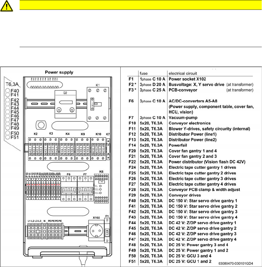
5.2.1 Overview of Electrics
Overview of Electrics
CAUTION
Observe the detailed circuit diagrams!
For more detailed information, refer to the circuit diagrams folder of your machine.
► SIPLACE SX4/DX4 detailed circuit diagrams [00196711-xx] (German/English)
► Circuit diagram SIPLACE X-Series S [00197021-xx] (German/English)
Settings
Electrical and Control Settings 5.2.2 Setting the Voltage on the Pulsed Power Packs
234 Service Manual SIPLACE SX4/DX4
5.2.2
5.2.2 Setting the Voltage on the Pulsed Power Packs
Setting the Voltage on the Pulsed Power Packs
Parts, equipment and tools
▪ Voltage measuring device
Overview
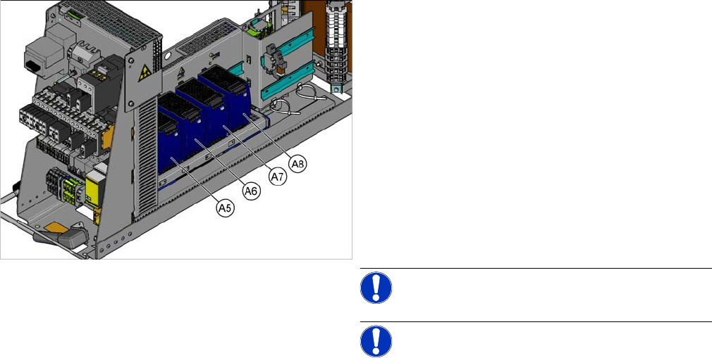
SX4 X34iS – Ov erview of Pul sed Power Pac ks
The pulsed power packs are located in the rack unit be-
tween location 3 and 4.
A5) Pulsed power pack (24 VDC, set to 25 VDC)
for Power Fail, safety circuit SSK, tape cutter, PCB Han-
dling
The power fail signal is generated by the pulsed power
pack A5 and sent to the GCU and HCU. (X200:9,
X200:10)
A6) Pulsed power pack (27 VDC)
for FCU (gantry 1 and 4)
A7) Pulsed power pack (27 VDC)
for FCU (gantry 2 and 3)
A8) Pulsed power pack (36 VDC, to be set to 42 VDC)
For HCU (gantry 1 to 4)
NOTICE!
NOTICE! Check the set values and correct if
necessary.
To A5:
The following fuses have 24 V present:
F10: Conveyor electrics
F11: Y motor fan, safety circuit (internal)
F12: Distributor power (line 1)
F13: Distributor power (line 2)
F14: Power fail
F20: Cover fan, gantry 1 and 4
F21: Cover fan, gantry 2 and 3
Settings
5.2.3 Overview of Station Computer Pneumatic Settings
Service Manual SIPLACE SX4/DX4 235
Setting
5.2.3
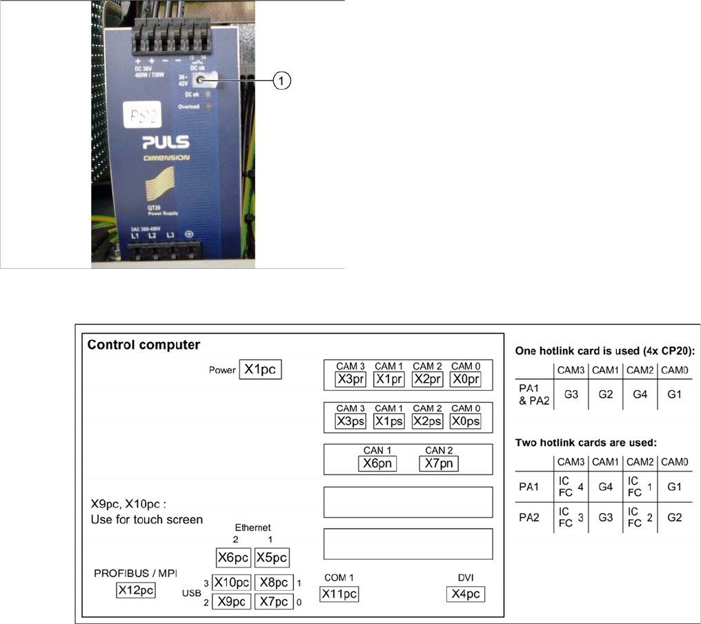
5.2.3 Overview of Station Computer
Overview of Station Computer
See also
6.1.1 I/O control unit [03052315-xx] [ ➙ 271]
5.3
5.3 Pneumatic Settings
Pneumatic Settings
5.3.1
5.3.1 Setting the Compressed Air Controller for Machine Components
Setting the Compressed Air Controller for Machine Components
► Make sure that the compressed air controller for machine components is set to 5.1 bar.
See also
2.7 Pneumatic System [ ➙ 26]
► Open the protective cap on the setting screw (1).
► Use a slotted screwdriver to set the correct voltage on
the pulsed power pack.
Check the voltage with a suitable voltage measuring
device, between the terminals + and –.