SIPLACE-SX4-DX4-用户手册.pdf - 第235页
Settings 5.2.3 Overview of Station Computer Pneumatic Settings Service Manual SIPLACE SX4/DX4 235 Setting 5.2.3 5 . 2 . 3 O v e r v ie w o f S t a t io n C o m p u t e r Overview of Station Computer See also 6.1.1 I/…
Settings
Electrical and Control Settings 5.2.2 Setting the Voltage on the Pulsed Power Packs
234 Service Manual SIPLACE SX4/DX4
5.2.2
5.2.2 Setting the Voltage on the Pulsed Power Packs
Setting the Voltage on the Pulsed Power Packs
Parts, equipment and tools
▪ Voltage measuring device
Overview
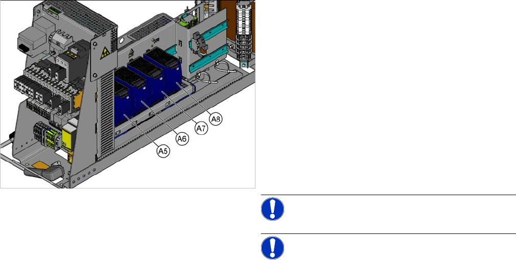
SX4 X34iS – Ov erview of Pul sed Power Pac ks
The pulsed power packs are located in the rack unit be-
tween location 3 and 4.
A5) Pulsed power pack (24 VDC, set to 25 VDC)
for Power Fail, safety circuit SSK, tape cutter, PCB Han-
dling
The power fail signal is generated by the pulsed power
pack A5 and sent to the GCU and HCU. (X200:9,
X200:10)
A6) Pulsed power pack (27 VDC)
for FCU (gantry 1 and 4)
A7) Pulsed power pack (27 VDC)
for FCU (gantry 2 and 3)
A8) Pulsed power pack (36 VDC, to be set to 42 VDC)
For HCU (gantry 1 to 4)
NOTICE!
NOTICE! Check the set values and correct if
necessary.
To A5:
The following fuses have 24 V present:
F10: Conveyor electrics
F11: Y motor fan, safety circuit (internal)
F12: Distributor power (line 1)
F13: Distributor power (line 2)
F14: Power fail
F20: Cover fan, gantry 1 and 4
F21: Cover fan, gantry 2 and 3
Settings
5.2.3 Overview of Station Computer Pneumatic Settings
Service Manual SIPLACE SX4/DX4 235
Setting
5.2.3
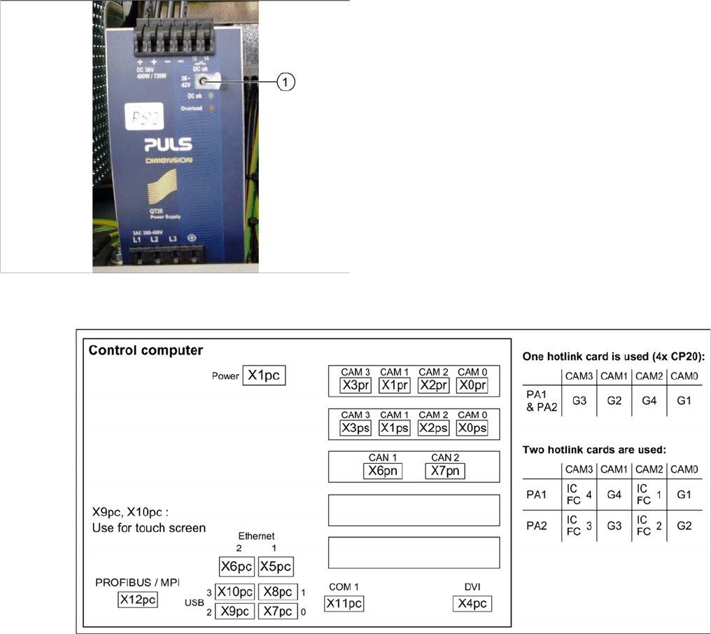
5.2.3 Overview of Station Computer
Overview of Station Computer
See also
6.1.1 I/O control unit [03052315-xx] [ ➙ 271]
5.3
5.3 Pneumatic Settings
Pneumatic Settings
5.3.1
5.3.1 Setting the Compressed Air Controller for Machine Components
Setting the Compressed Air Controller for Machine Components
► Make sure that the compressed air controller for machine components is set to 5.1 bar.
See also
2.7 Pneumatic System [ ➙ 26]
► Open the protective cap on the setting screw (1).
► Use a slotted screwdriver to set the correct voltage on
the pulsed power pack.
Check the voltage with a suitable voltage measuring
device, between the terminals + and –.
Settings
Gantry Settings 5.4.1 Travel Ranges and Speed Monitoring
236 Service Manual SIPLACE SX4/DX4
5.4
5.4 Gantry Settings
Gantry Settings
5.4.1
5.4.1 Travel Ranges and Speed Monitoring
Travel Ranges and Speed Monitoring
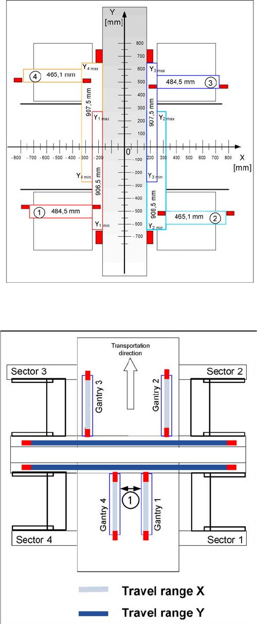
The travel range of the X and Y axes will be determined during machine calibration.
Travel range for X and Y axes (X series shown as exam
-
ple)
1) to 4) = gantry 1 to 4
The end of the X axis travel range is + or - 0.5 mm before
the software limit switch, which is 1.5 mm before the buff-
er. A safety distance of 2.0 mm to the buffer is adequate,
if the X axis moves into this area with excessive speed.
The end of the Y axis travel range is + or - 2.0 mm before
the software limit switch. The Y axis travel range for a
particular placement area is monitored in one direction by
the software limit switch and a buffer. In the other direc-
tion, there is a permanent exchange of communication
between the axes and their positions, via the SPI Bus
(see description of the anticrash function).
Travel range for X and Y axes (X series shown as exam
-
ple)
1. Safety distance between the gantries during place-
ment: minimum 4mm.
Depending on the placement mode (i-placement or alter-
nating), the gantries will operate in one placement area
fully independently. This means that one gantry does not
need to know the position of the other one.