SIPLACE-SX4-DX4-用户手册.pdf - 第238页
Settings Gantry Settings 5.4.5 Mechanical Adjustment of the Incremental E ncoder 238 Service Manual SIPLACE SX4/DX4 5.4.5 5 . 4 . 5 M e c h a n ic a l A d ju s t m e n t o f t h e I n c r e m e n t a l E n c o d e r Mech…
Settings
5.4.2 Error "Gantry Crash" Gantry Settings
Service Manual SIPLACE SX4/DX4 237
5.4.2
5.4.2 Error "Gantry Crash"
Error "Gantry Crash"
A “gantry crash” error is established by calculating the position difference and speed difference for both
axes. A gantry crash error is signaled via the GCUs and the CAN Bus. After the "gantry crash" error mes-
sage has been issued, both gantries need to be referenced.
5.4.3
5.4.3 Count Error:
Count Error:
If the GCU detects a "fatal count error", the axis concerned will be released and the anticrash function
disabled. The other axis is informed of this in the status information and will also disable the anticrash
function. The released axis now needs to be referenced again.
After this, the anticrash function will be re-enabled for both axes.
5.4.4
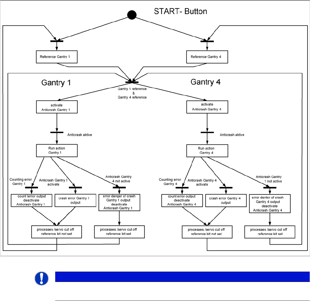
5.4.4 Anticrash Function
Anticrash Function
Example of the anticrash function sequence in placement area 1
NOTICE
GCU, HCU
The GCU and the HCU consist of a control module (axis card) and a power module (servo).
Settings
Gantry Settings 5.4.5 Mechanical Adjustment of the Incremental Encoder
238 Service Manual SIPLACE SX4/DX4
5.4.5
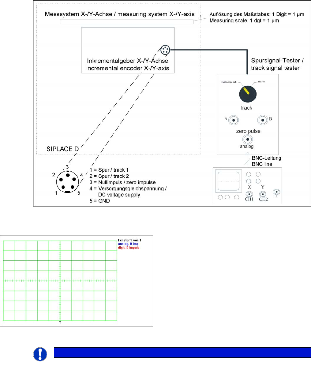
5.4.5 Mechanical Adjustment of the Incremental Encoder
Mechanical Adjustment of the Incremental Encoder
The incremental encoders (read units) on the X and Y axis are adjusted exactly to the position of the
incremental scale. The two limit marks on the incremental encoder show where the top/bottom positions
of the scale should be. Depending on the machine type, they are also mechanically set to a distance of
0.75 mm (black-white scale) or 0.4 mm (golden scale) to the incremental scale.
--- = Combination not possible, X = combination possible
After this adjustment of the incremental encoder you have to check the zero pulse and track signals.
Correct installation should ensure correct count and zero pulse signals. For troubleshooting purposes
(error analysis and fixing), you will need to measures these signals.
Please also observe section Track Signals and Zero Pulse.
See also
5.4.6 Track Signals and Zero Pulse [ ➙ 239]
Machine type Black-white scale
(0.75 mm)
Gold scale
(0.4 mm)
X-Series S X ---
SX4/DX4 X X
NOTICE
Plastic disks
To set this distance, use one or more small plastic disks with a total thickness of 0.75 (or
0.4 mm).
► Feeler gauge 0.75 mm plastic [03090774-xx]
Settings
5.4.6 Track Signals and Zero Pulse Gantry Settings
Service Manual SIPLACE SX4/DX4 239
5.4.6
5.4.6 Track Signals and Zero Pulse
Track Signals and Zero Pulse
5.4.6.1
5.4.6.1 Checking the Zero Pulse Signal
Checking the Zero Pulse Signal
The zero pulse must be reliably and clearly recognized by the read head. To ensure this, you can check
both the analog and the digital zero pulse. Electronically controlled settings can not be performed on the
incremental length measurement system.
Measuring the Analog Zero Pulse Signal
Measurement procedure for checking the analog zero pulse and the analog track signals
Measurement Procedure
Measuring the initial zero pulse position
► Connect the measurement tester to the incremental
encoder.
► Main power switch ON
► Connect the oscilloscope to the measurement tester.
► Set the measuring adapter to Calibrate the oscillo-
scope and position the signal at the top center of the
screen.
NOTICE
Verification
Check the first zero pulse after the limit switch.