SIPLACE-SX4-DX4-用户手册.pdf - 第244页
Settings Gantry Settings 5.4.6 Track Signals and Zero Pulse 244 Service Manual SIPLACE SX4/DX4 5.4.6.3 5 . 4 . 6 . 3 T e s t D e v ic e P G 1 - I ( M S 2 2 / M S 3 0 ) [ 0 3 1 0 2 6 9 9 - x x ] – O p e r a t io n Test De…
Settings
5.4.6 Track Signals and Zero Pulse Gantry Settings
Service Manual SIPLACE SX4/DX4 243
Digital Track Signals
To check the digital track signals, connect the track signal tester and the oscilloscope. (see "5.4.6.1.2
Measuring the Digital Zero Pulse Signal" [ ➙ 241])
The measurement sequence is identical to that described in "5.4.6.2.1 Analog Track Signals" [ ➙ 242].
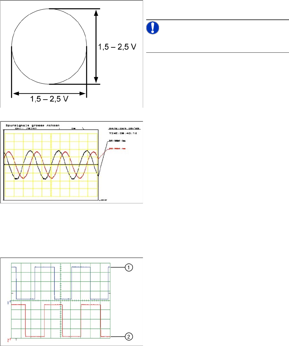
Analog track signals A and B in X/Y oscilloscope mode
► The adjacent picture should appear on the oscillo-
scope.
NOTICE!
A new version of the incremental encoder (one field lens)
can recognize signals from 1.8 to 3.6 Vss.
Analog track signals 90° phase shift
► Switch the oscilloscope to normal operation.
► The adjacent picture should appear on the oscillo-
scope.
Digital track signals 90° phase shift
1. Track A
2. Track B
Settings
Gantry Settings 5.4.6 Track Signals and Zero Pulse
244 Service Manual SIPLACE SX4/DX4
5.4.6.3
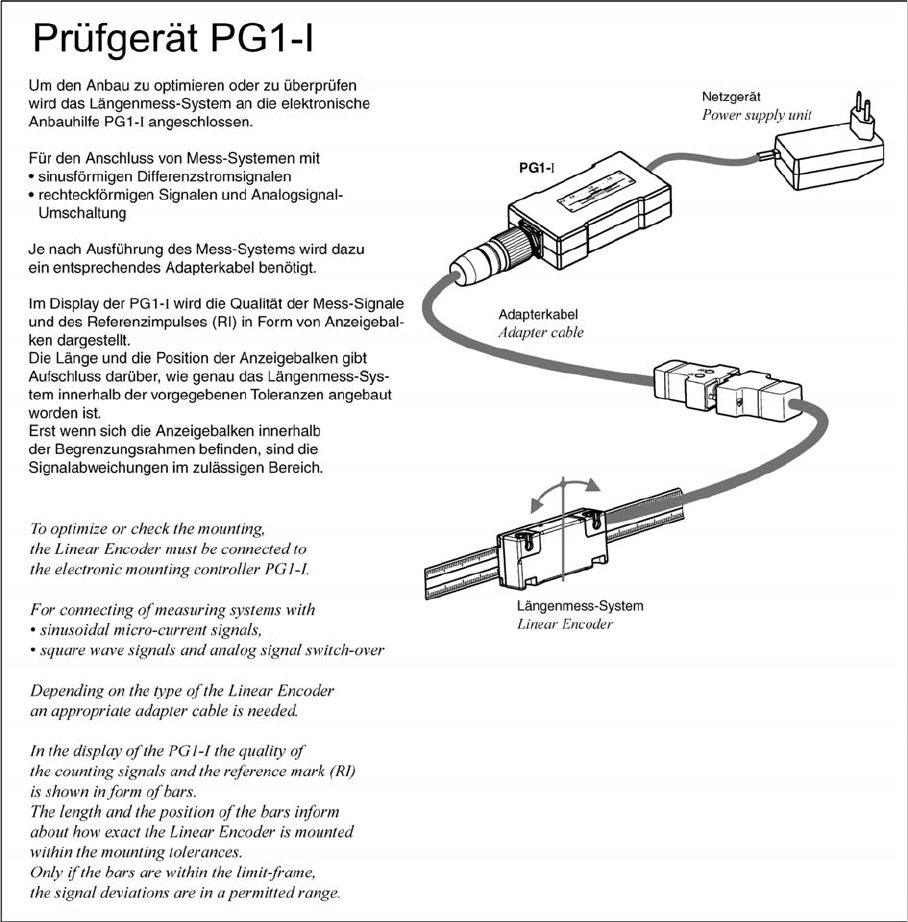
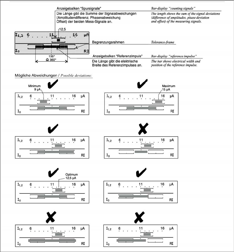
5.4.6.3 Test Device PG1-I (MS22/MS30) [03102699-xx] – Operation
Test Device PG1-I (MS22/MS30) [03102699-xx] – Operation
Settings
5.4.6 Track Signals and Zero Pulse Gantry Settings
Service Manual SIPLACE SX4/DX4 245