SIPLACE-SX4-DX4-用户手册.pdf - 第255页
Settings 5.5.1 Belt Tension Conveyor Settings Service Manual SIPLACE SX4/DX4 255 5.5.1.4 5 . 5 . 1 . 4 C a lc u la t in g t h e B e lt T e n s io n Calculating the Belt Tension Example Distance between the r ollers: 235 …
Settings
Conveyor Settings 5.5.1 Belt Tension
254 Service Manual SIPLACE SX4/DX4
Setting
See also
3.6.1 Loosening the Conveyor Side Clamps [ ➙ 95]
3.6.1 Loosening the Conveyor Side Clamps [ ➙ 95]
1.2 Preparatory Work... [ ➙ 12]
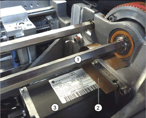
Conveyor drive (using example of SX1/SX2)
► Clamp the flat spiral spring (2) between the motor (3)
and the shaft above it (1). While doing so, push the
flat spiral spring as far as possible in the direction of
the conveyor side. The flat spiral spring must lie flush
on the motor, as shown in the diagram. The shaft
should be set so that its flat side is in the flat spiral
spring.
► Tighten the screws fastening the motor.
⇨ The tension of the flat spiral spring and the weight of
the motor should now have set the belt tension cor-
rectly to 250 +/-20 Hz.
Settings
5.5.1 Belt Tension Conveyor Settings
Service Manual SIPLACE SX4/DX4 255
5.5.1.4
5.5.1.4 Calculating the Belt Tension
Calculating the Belt Tension
Example
Distance between the rollers: 235 mm
Calculation:
20000/235 = 85 (exactly 85.106…)
10 % of 85.106… = 8.5106…
Result:
Belt tension: 85 +/-9 Hz
NOTICE
For conveyor belt only
This calculation only applies to the conveyor belt.
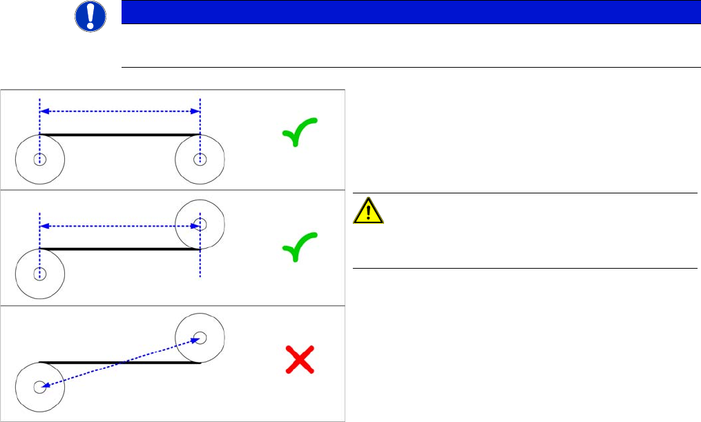
► Define the two deflection pulleys between which you
want to set the belt tension. If possible, avoid using
the idlers for this.
► Measure the distance between the two deflection pul-
leys parallel to the conveyor belt. (see diagram)
CAUTION!
Please note that it is not always possible to just measure
the deflection pulleys from center to center.
► Calculate the belt tension using the following formula:
(20000 / roller spacing [mm]) [Hz]
The permissible tolerance is always plus/minus 10 % of
the calculated value.
Settings
Conveyor Settings 5.5.2 Teaching the Sonar Sensor PXS240
256 Service Manual SIPLACE SX4/DX4
5.5.2
5.5.2 Teaching the Sonar Sensor PXS240
Teaching the Sonar Sensor PXS240
Parts, equipment and tools
▪ Setting gauge for ultrasonic sensors [03076989-xx]
▪ Programming cable for PXS240 sensor [03073330-xx]
Setting
► Use the software to move the conveyor sides into the position which allows you best access. As an
alternative, you can loosen the clamps for the relevant sides in dual conveyors.
► Secure the machine by attaching relevant warning tags. Do not switch the machine off as the setting
would then not be applied. Observe the instructions in section "1.2 Preparatory Work..." [ ➙ 12],
NOTICE
2 versions of the programming cable
In the meantime, a second version of the programming cable (UB-PROG2) has been supplied.
The function of this programming cable is similar to that of programming cable PXS240. Fur-
thermore, two adapter cables (M8/M12 adapter and M12/M8 adapter) can be connected for the
sensor and the conveyor control cable.
The previous programming cable will now be available under the name "UB-PROG4-V31" (old
name was PXS240) and the item no.: [03073330-xx].
► See also"4.10 Programming Cable for PXS240 Sensor [03073330-xx]" [ ➙ 223]
► To use the new programming cable, proceed as follows:
Switch on the machine and place the gauge onto the conveyor, as described. To teach,
press the "A1" button on the programming cable for approx. 3 seconds, until the LED on the
sensor begins to flash. The "A2" button on the UB-PROG2 is not needed.
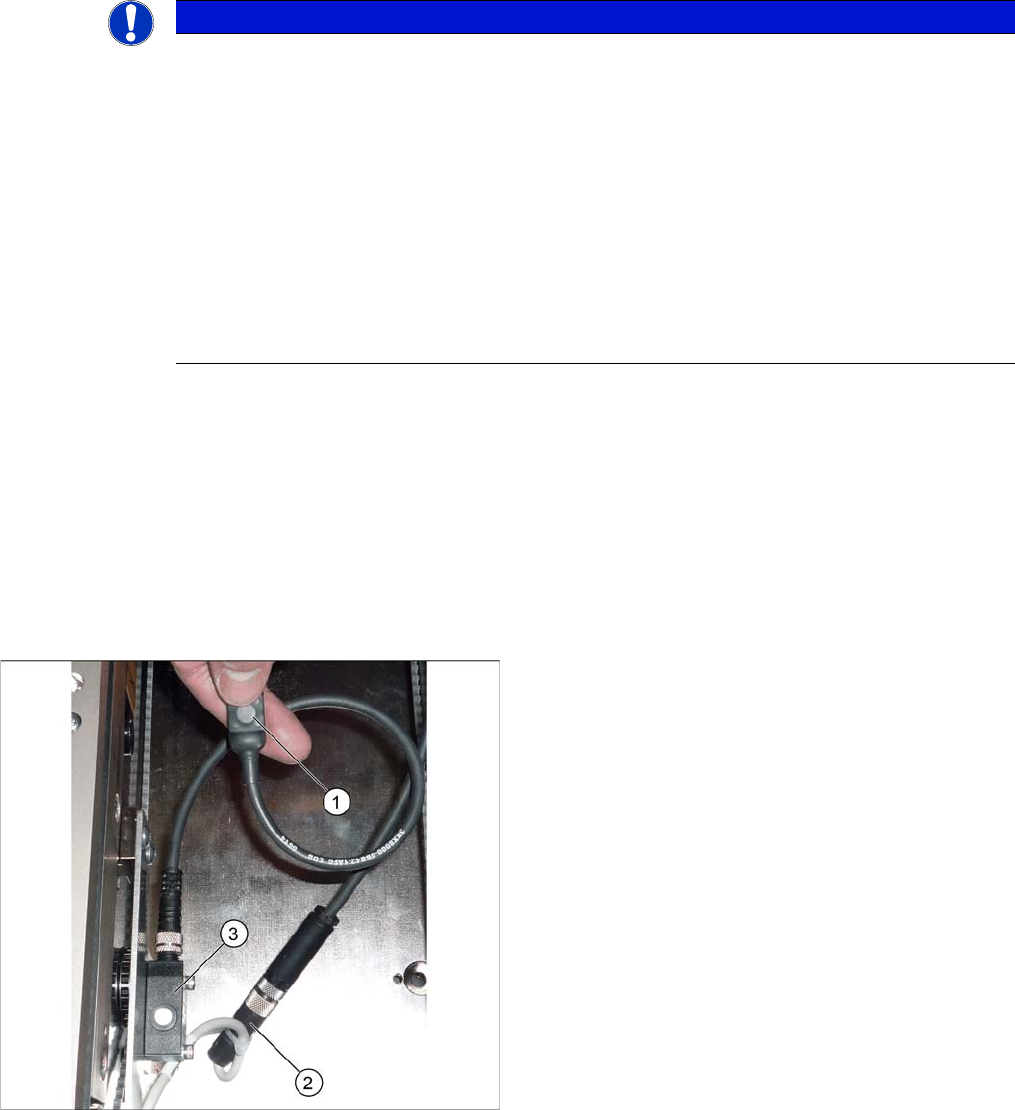
Connecting the programming cable (example of X4I
shown)
1. Programming cable for PXS240 ultrasonic sensor
2. Press-fit connection for the ultrasonic sensor
3. Ultrasonic sensor PXS240
► Unplug the press-fit connection from the ultrasonic
sensor and connect the programming cable between
this and the ultrasonic sensor.