SIPLACE-SX4-DX4-用户手册.pdf - 第258页
Settings Conveyor Settings 5.5.3 Conveyor Sides 258 Service Manual SIPLACE SX4/DX4 5.5.3 5 . 5 . 3 C o n v e y o r S id e s Conveyor Sides 5.5.3.1 5 . 5 . 3 . 1 S e t t in g t h e P a r a lle lis m o f t h e S in g le C …
Settings
5.5.2 Teaching the Sonar Sensor PXS240 Conveyor Settings
Service Manual SIPLACE SX4/DX4 257
► To teach, press the button on the programming cable for approx. 3 seconds, until the LED on the
sensorbegins to flash.
The switching threshold is set accordingly.
► Remove the setting gauge.
► Loosen the programming cable connections and reconnect the ultrasonic sensor directly to the con-
nection at the machine end.
See also
3.6.1 Loosening the Conveyor Side Clamps [ ➙ 95]
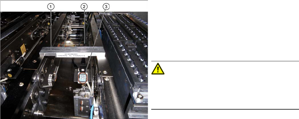
Fitted ultrasonic sensor with programming cable and ad
-
justment gauge (example of X4I shown)
1. Setting gauge
2. Programming cable (fitted)
3. LED on ultrasonic sensor
► The distance to the PCB is defined with the setting
gauge.
Position the setting gauge over the conveyor, so that
it is above the reception area of the ultrasonic sensor.
CAUTION!
Make sure that the gauge is used the right way round.
The gauges can be used for different conveyor types.
Make sure that the gauges are always used the right way
round.
▪ 3mm gap for the X conveyor
▪ 2mm gap for the SX conveyor
Settings
Conveyor Settings 5.5.3 Conveyor Sides
258 Service Manual SIPLACE SX4/DX4
5.5.3
5.5.3 Conveyor Sides
Conveyor Sides
5.5.3.1
5.5.3.1 Setting the Parallelism of the Single Conveyor Sides
Setting the Parallelism of the Single Conveyor Sides
Overview
Setting
► Use the software to move the conveyor side into the position which allows you best access.
► Switch off the machine, disconnect it from the power supply and secure it to prevent unauthorized
reactivation. Observe the instructions in section "1.2 Preparatory Work..." [ ➙ 12].
► Loosen the screws fastening the width adjustment drive. The toothed belt of the width adjustment
should then have enough play so that you can move the width adjustment units independently of one
another. You may need to loosen the toothed belt from the deflection pulleys.
► Push the conveyor side manually to its outermost position, so that the adjustment units are posi-
tioned against the spindle stops.
► If you have loosened the toothed belt from the deflection pulleys, insert this again now.
► Tighten the screws fastening the drive again and set the belt tension to 27 +/-2 Hz. (see "5.5.1.2 Set-
ting the Width Adjustment Belt Tension" [ ➙ 252]).
Verification
► The flexible conveyor side must have the same distance to the mounting frame at all points.
► Pull the toothed belt to move the flexible conveyor side manually as far as the edge. The adjustment
units must touch the stops at the same time.
► Calibrate the width adjustment motor.
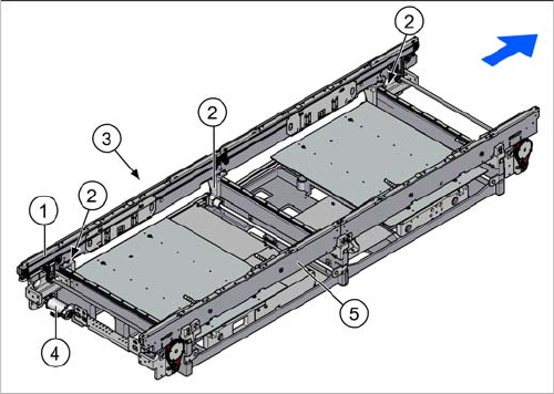
1. Flexible conveyor side wall (shown on the left here)
2. Adjustment units (3x)
3. Toothed belt of width adjustment
4. Width adjustment drive
5. Fixed conveyor side (shown on the right here)
Settings
5.5.3 Conveyor Sides Conveyor Settings
Service Manual SIPLACE SX4/DX4 259
5.5.3.2
5.5.3.2 Setting the Parallelism of the Dual/Quad Conveyor Sides/Adjustment Units
Setting the Parallelism of the Dual/Quad Conveyor Sides/Adjustment Units
Overview
Setting
► Use the software to move the conveyor sides into the position which allows you best access. As an
alternative, you can loosen the clamps for the relevant sides in dual conveyors.
► Switch off the machine, disconnect it from the power supply and secure it to prevent unauthorized
reactivation. Observe the instructions in section "1.2 Preparatory Work..." [ ➙ 12].
► Loosen the screws fastening the width adjustment drive. The toothed belt of the width adjustment
should then have enough play so that you can move the adjustment units independently of one an-
other. You may need to loosen the toothed belt from the deflection pulleys.
► Push the adjustment units manually to their outermost position, so that the adjustment units are po-
sitioned against the spindle stops.
► If you have loosened the toothed belt from the deflection pulleys, insert this again now.
► Tighten the screws fastening the drive again and set the belt tension to 27 +/-2 Hz. (See "5.5.1.2
Setting the Width Adjustment Belt Tension" [ ➙ 252])
► If the conveyor side clamps have loosened, fix these again.
Check
Check the parallelism of the conveyor sides.
► Measure and compare the distance of the adjustment units to the stops. The distance must be the
same at all adjustment units.
► Pull the toothed belt to move the adjustment units manually as far as the edge. The adjustment units
must touch the stops at the same time.
See also
3.6.1 Loosening the Conveyor Side Clamps [ ➙ 95]
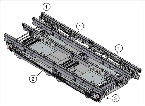
1. Adjustment unit (3x)
2. Toothed belt of width adjustment
3. Width adjustment drive