SIPLACE-SX4-DX4-用户手册.pdf - 第264页
Settings Nozzle Changer Setting 5.6.3 Jumpers on the Nozzle Change r 264 Service Manual SIPLACE SX4/DX4 5.6.3 5 . 6 . 3 J u m p e r s o n t h e N o z z le C h a n g e r Jumpers on the Nozzle Changer The jumper X10 need s…
Settings
5.6.1 Setting the Nozzle Changer Height Nozzle Changer Setting
Service Manual SIPLACE SX4/DX4 263
5.6
5.6 Nozzle Changer Setting
Nozzle Changer Setting
5.6.1
5.6.1 Setting the Nozzle Changer Height
Setting the Nozzle Changer Height
Parts, equipment and tools
▪ NC shim plate [03021079-xx]
▪ NC support plate [03021044-xx]
▪ Screws DIN 965-M4 x 10-4.8 [00095312-xx]
Settings
5.6.2
5.6.2 Setting the Height of the Nozzle Reject Station
Setting the Height of the Nozzle Reject Station
Parts, equipment and tools
▪ Shim plates for nozzle reject device [03039514-xx]
Settings
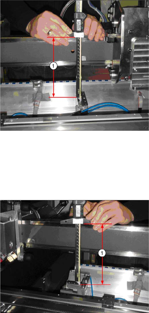
► The distance (1) between the contact surface of the
reject unit and the guidance rail of the gantry needs
to be 200 +/-0.2 mm.
You may need to use shim plates to adjust this.
► The distance (1) between the contact surface of the
nozzle reject station and the guidance rail of the gan-
try needs to be 189 +/-0.2 mm.
You may need to use shim plates to adjust this.
Settings
Nozzle Changer Setting 5.6.3 Jumpers on the Nozzle Changer
264 Service Manual SIPLACE SX4/DX4
5.6.3
5.6.3 Jumpers on the Nozzle Changer
Jumpers on the Nozzle Changer
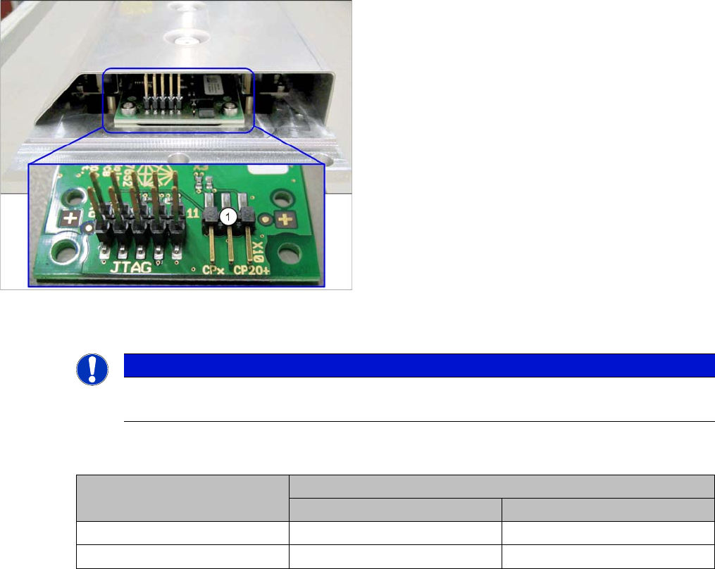
The jumper X10 needs to be set at the following nozzle changers:
▪ Nozzle changer basic structure CPx/all assembly - short [03103649-xx]
▪ Nozzle changer basic structure CPx/all assembly - long [03103514-xx]
Overview
Setting
► Set the correct value for your head type and software.
Nozzle Changer CP20P - Jumper X10
Jumper X10
See also
6.6.2 Nozzle Changer Main Board C&P20P [03107652-xx] [ ➙ 295]
1. Jumper X10
NOTICE
Before installation
Due to the design, this setting must be performed before installation in the machine.
Head Jumper position
SW <= 706.x SW >= 707.x
CPx, DLM 1-2 1-2 or 2-3
C&P20 P --- 2-3 (factory settings)
Settings
5.7.1 Setting the Actuator on the Component Trolley Settings on the Component Trolley
Service Manual SIPLACE SX4/DX4 265
5.7
5.7 Settings on the Component Trolley
Settings on the Component Trolley
5.7.1
5.7.1 Setting the Actuator on the Component Trolley
Setting the Actuator on the Component Trolley
Parts, equipment and tools
▪ Allen key
Setting
See also
3.11.6 Replacing the Actuator/Protective Bracket [ ➙ 189]
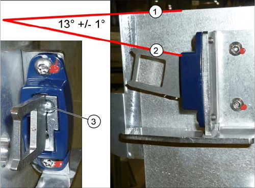
► Set the actuator with the help of the grub screw (3).
Between the upper edge (1) of the table and the
actuator (2) you need to set an angle of 13° +/- 1°.
The actuator must be able to slide into the safety
switch without rubbing against the plastic.