SIPLACE-SX4-DX4-用户手册.pdf - 第271页
Description of the circuit boards 6.1.1 I/O control unit [03052315-xx] Electrics and Control Service Manual SIPLACE SX4/DX4 271 6 6 D e s c r ip t io n o f t h e c ir c u it b o a r d s Description of the circuit boards …
Settings
Other Settings 5.8.4 DIP Switch for Camera Types 25 and 33
270 Service Manual SIPLACE SX4/DX4
5.8.4
5.8.4 DIP Switch for Camera Types 25 and 33
DIP Switch for Camera Types 25 and 33
Setting
► Switch off the machine, disconnect it from the power supply and secure it to prevent unauthorized
reactivation. Observe the instructions in section "1.2 Preparatory Work..." [ ➙ 12].
► Remove the camera upper part and the cover on the lower part, to gain access to the DIP switches.
► Set the DIP switches. (see below)
► Fit all parts by following the above instructions in the reverse order.
DIP switch
Boards with version status 01 and 02 are fitted with a TQ module. In this case, the DIP switching block
is 8 pin.
Boards with version status 03 or higher do not have a TQ module. In this case, the DIP switching block
is 6 pin.
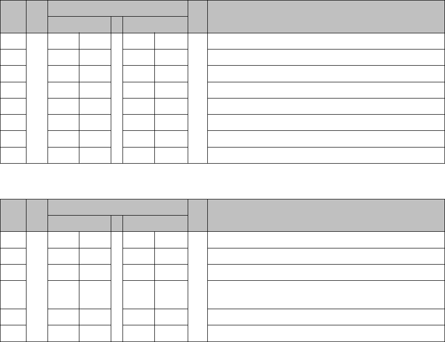
Version state 01 and 02: DIP switch settings (8 pin)
* Not all gantries may be available, depending on the machine type.
Version state 03 and higher: DIP switch settings (6 pin)
* Not all gantries may be available, depending on the machine type.
See also
6.5.1 Vision LED driver VLT 33 [03039244-xx] [ ➙ 293]
S Setting for gantry* Comments
1 2
1OFFOFFBootstrap
2OFFOFFReset
3OFFOFFGantry ID 0
4OFFONGantry ID 1
5OFFOFFTest
6OFFOFFCAN terminator
7ON ON CAN speed: ON: 1 Mbit/s, OFF: 500 KB/s
8 xx xx OFF: FC camera (type 25), ON: IC camera (type 33)
S Setting for gantry* Comments
1 2
1OFFOFFReset
2OFFOFFGantry ID 0
3OFFONGantry ID 1
4 x x x x LED: This switch is delivered with a fixed presetting.
Do not change this setting!
5OFFOFFCAN terminator
6 xx xx OFF: FC camera (type 25), ON: IC camera (type 33)
Description of the circuit boards
6.1.1 I/O control unit [03052315-xx] Electrics and Control
Service Manual SIPLACE SX4/DX4 271
6
6 Description of the circuit boards
Description of the circuit boards
6.1
6.1 Electrics and Control
Electrics and Control
6.1.1
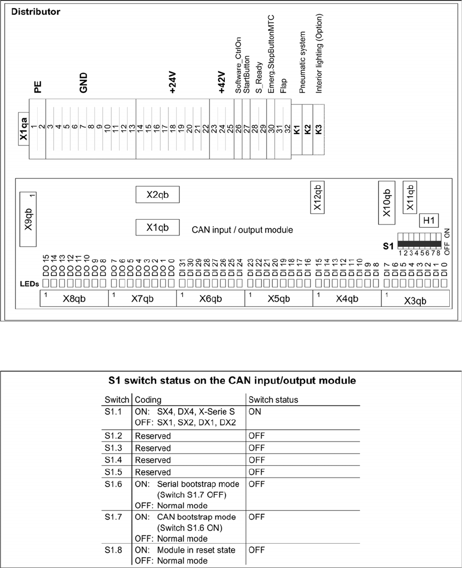
6.1.1 I/O control unit [03052315-xx]
I/O control unit [03052315-xx]
03052315-02
DIP switch block S1 [03052315-02]
Description of the circuit boards
Electrics and Control 6.1.1 I/O control unit [03052315-xx]
272 Service Manual SIPLACE SX4/DX4
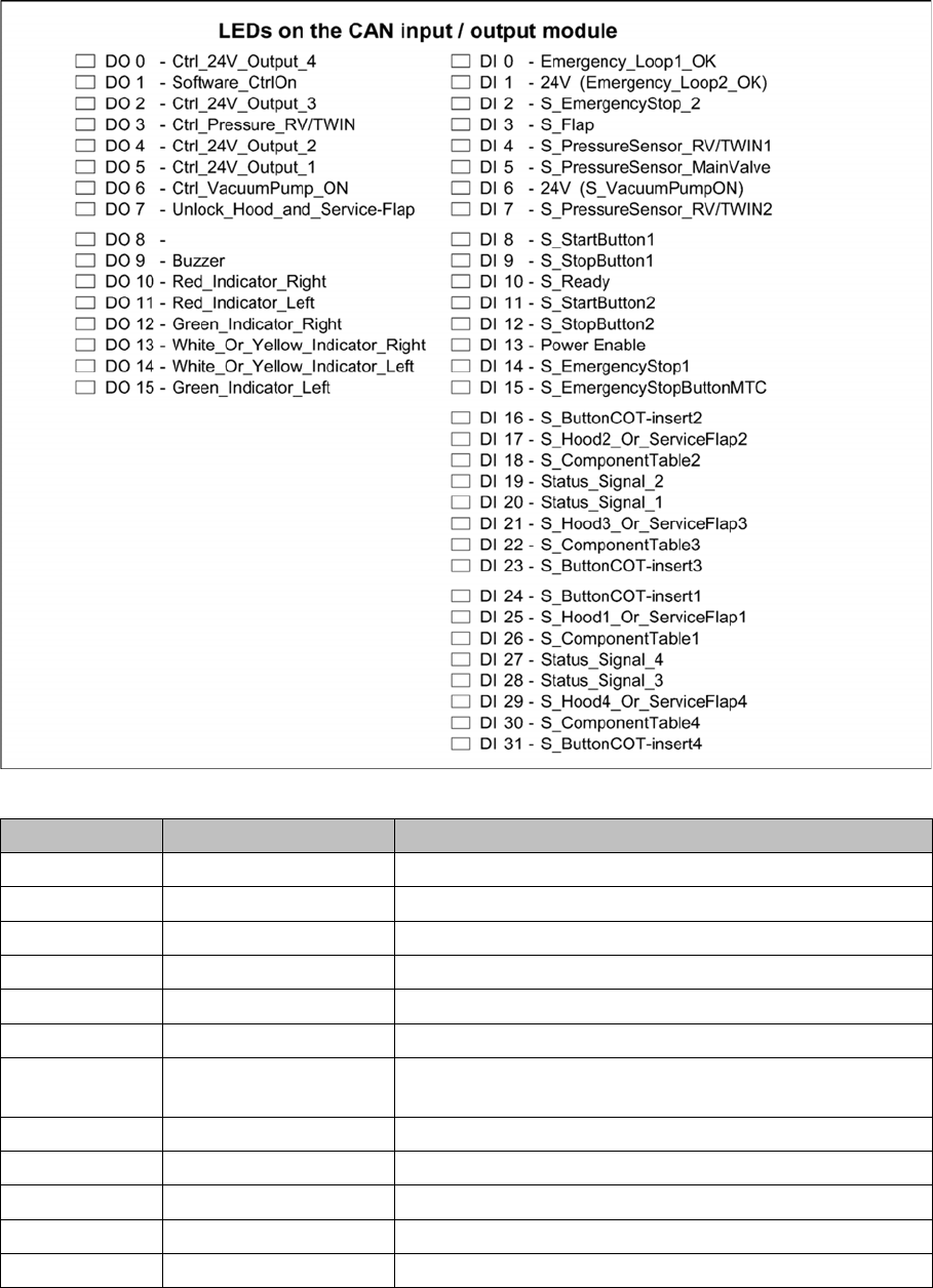
LEDs [03052315-02]
7-segment display H1 [03052315-02]
Display Status Description
Dot Flashes Circuit board OK
0 ON Firmware OK
1 ON CAN telegram cannot be transmitted
2 ON FW error: overflow in the CAN bus receiver buffer
3 ON CAN bus controller in the status ERROR PASSIVE
4 ON CAN bus controller in the status BUS OFF
5 ON Processor board received a message instead of a com-
mand
6 ON PowerFail signal active
F ON Other error
Any ON Hardware problem
A ON When initializing: BIOS mode changes to application mode
b ON When booting: head processor remains in BIOS mode