SIPLACE-SX4-DX4-用户手册.pdf - 第272页
Description of the circuit boards Electrics and Control 6.1.1 I/O control unit [0 3052315-xx] 272 Service Manual SIPLACE SX4/DX4 LEDs [03052315-02] 7-segment disp lay H1 [03052315- 02] Display Status Description Dot Flas…
Description of the circuit boards
6.1.1 I/O control unit [03052315-xx] Electrics and Control
Service Manual SIPLACE SX4/DX4 271
6
6 Description of the circuit boards
Description of the circuit boards
6.1
6.1 Electrics and Control
Electrics and Control
6.1.1
6.1.1 I/O control unit [03052315-xx]
I/O control unit [03052315-xx]
03052315-02
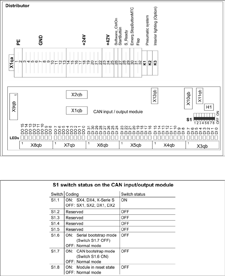
DIP switch block S1 [03052315-02]
Description of the circuit boards
Electrics and Control 6.1.1 I/O control unit [03052315-xx]
272 Service Manual SIPLACE SX4/DX4
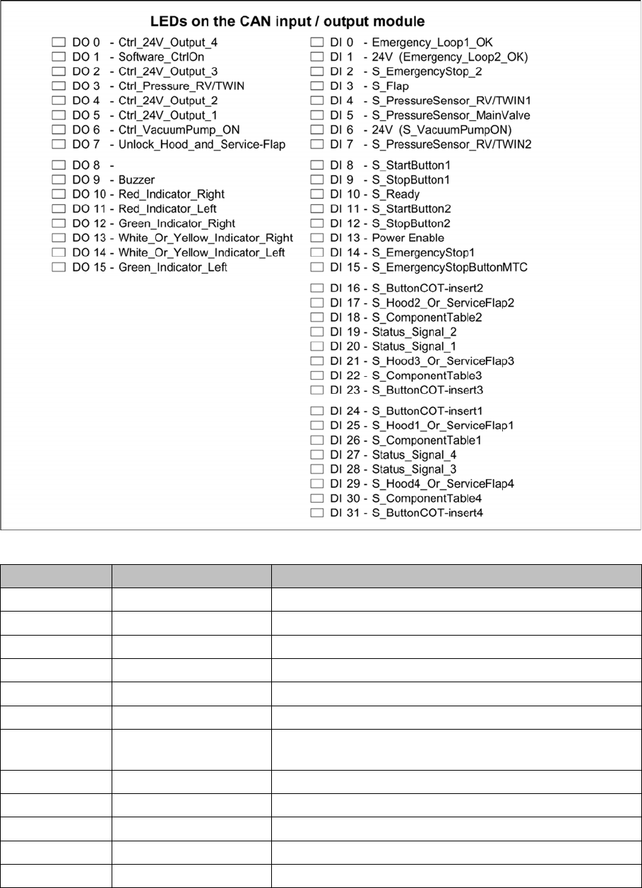
LEDs [03052315-02]
7-segment display H1 [03052315-02]
Display Status Description
Dot Flashes Circuit board OK
0 ON Firmware OK
1 ON CAN telegram cannot be transmitted
2 ON FW error: overflow in the CAN bus receiver buffer
3 ON CAN bus controller in the status ERROR PASSIVE
4 ON CAN bus controller in the status BUS OFF
5 ON Processor board received a message instead of a com-
mand
6 ON PowerFail signal active
F ON Other error
Any ON Hardware problem
A ON When initializing: BIOS mode changes to application mode
b ON When booting: head processor remains in BIOS mode
Description of the circuit boards
6.1.2 Inrush Current Limitation Board Transformer (A1) [03066830-xx] Electrics and Control
Service Manual SIPLACE SX4/DX4 273
6.1.2
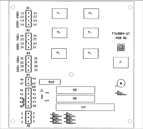
6.1.2 Inrush Current Limitation Board Transformer (A1) [03066830-xx]
Inrush Current Limitation Board Transformer (A1) [03066830-xx]
03066830-01
Jumper J1:
HF/X series: jumper to ON
SX4: jumper to OFF
SX1/SX2: The jumper is not queried here. The jumper
setting is therefore irrelevant.